TM 5-4310-452-14
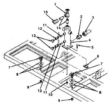
4-103. HOSE REEL ASSEMBLY SUPPORT BRACKET AND COUPLING REPLACEMENT (Con't).
5.
Remove 4 self-locking bolts (5), nuts (10), and hose reel support bracket (4) from frame. Discard self-locking bolts
and nuts.
6.
Remove drain cock (6) from bottom of hose reel support bracket (4).
b.
INSTALLATION
1.
Install drain cock (6) in bottom of hose reel support bracket (4).
2.
Install 2 coupling halves (7), 4 flat washers (8), and 2 pipe caps (9) on frame.
3.
Position hose reel support bracket (4) in place on frame and install 4 new self-locking bolts (5) and nuts (10).
4.
Install adapter (2) in hose reel support bracket (4). Connect air discharge hose assembly (3) to adapter.
5.
Install 2 nipples (11), ball valves (12), and coupling halves (13) on hose reel support bracket (4).
6.
Install 2 nipples (14), angle valve (1), and coupling half (15) on hose reel support bracket (4).
FOLLOW-ON TASKS:
• Install hose reels (see paragraph 4-102).
TA505560
4-214