• Home
  • Download PDF
  • Order CD-ROM
  • Order in Print
Figure 1-6. Hydraulic brake system schematic diagram.
Chapter 2. INSTALLATION AND OPERATING INSTRUCTIONS - TM-5-4930-207-120025

TM-5-4930-207-12 Lubricating and Servicing Unit Power Operated Trailer Mounted 23 CFM Compressor Reciprocating Gasoline Driven (Henry Spen Model 901765-1) Manual
Page Navigation
  5    6    7    8    9  10  11    12    13    14    15  
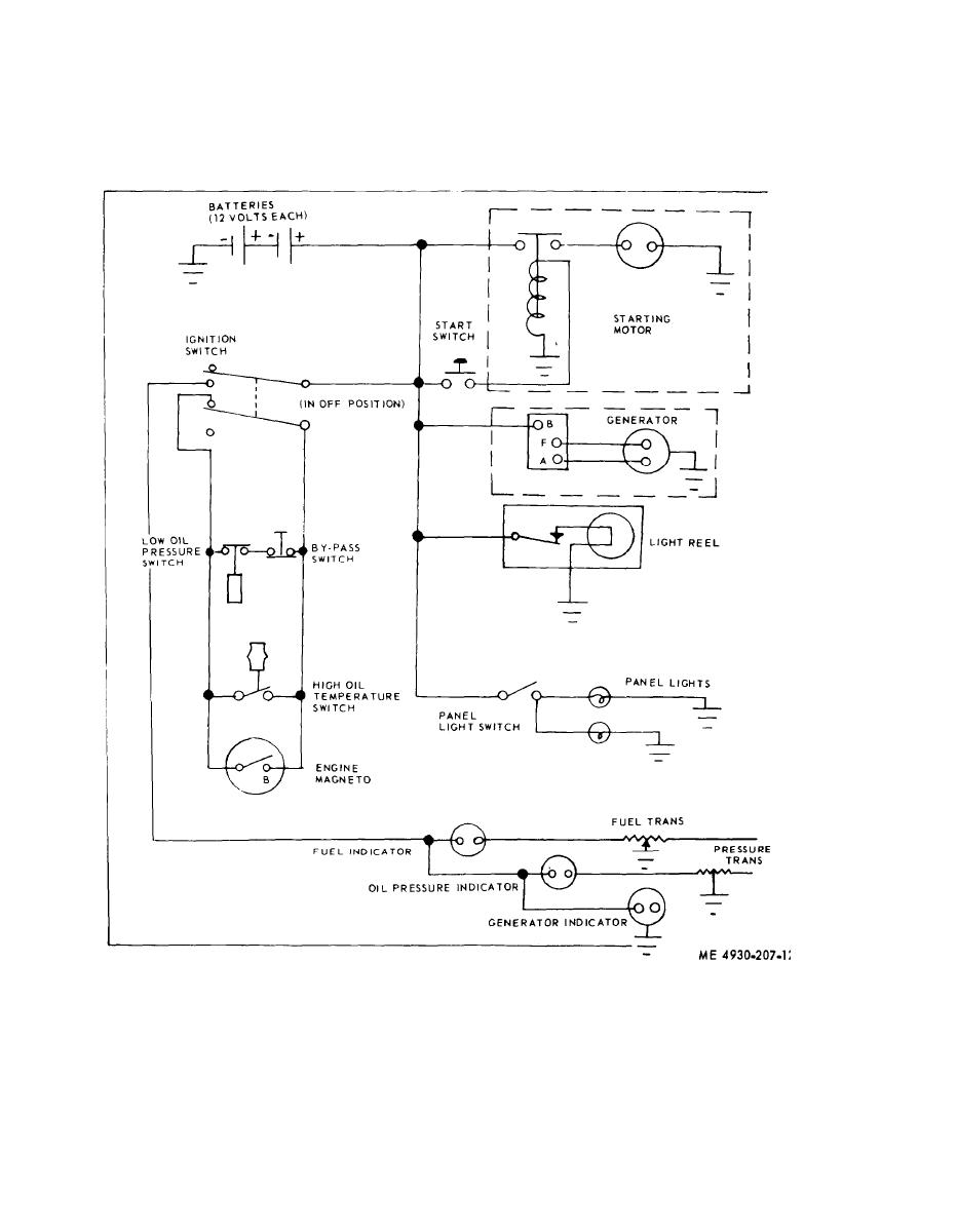
(17) Lubricator wiring diagram. Refer to figure
1-7 for the lubricator schematic wiring diagram.
Figure 1-7. Lubricator schematic wiring diagram.
1-6. Difference in Models
lubricating and servicing unit. No known unit differ-
ences exist for the model covered by this manual.
This manual covers only the Henry Spen and Co.
1-10


Western Governors University

Privacy Statement
Press Release
Contact

© Copyright Integrated Publishing, Inc.. All Rights Reserved. Design by Strategico.