
tank (27).
(2) Disconnect the fuel transmitter (33) at the
(3) Service the fuel tank.
fuel tank (27).
(3) Remove the fuel tank, fuel filter and lines in
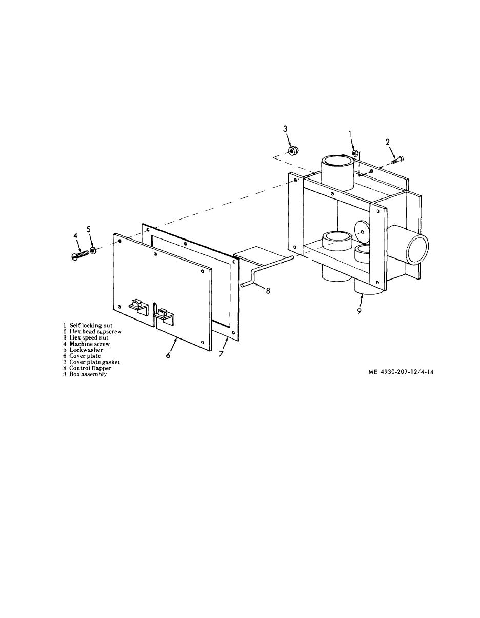
4-21. Exhaust Diverter Valve
numerical sequence as illustrated in figure 4-13.
a. Removal.
b. Installation.
(1) Loosen two clamps on each of the three ex-
(1) Install the fuel tank, fuel lines and fuel filter
haust hoses and remove the hoses.
in the reverse of numerical sequence as illustrated
(2) Remove the exhaust diverter valve in numeri-
in figure 4-13.
cal sequence as illustrated in figure 4-14.
(2) Connect the fuel transmitter (3) at the fuel
Figure 4-14. Exhaust diverter valve, removal and installation.
c. Installation.
b. Inspection and Repair.
(1) Install the exhaust diverter valve in the re-
(1) Inspect the exhaust hoses for leakage and
verse of numerical sequence as illustrated in figure
rust.
4-14.
(2) Inspect exhaust diverter valve for cracks,
(2) Install the three exhaust hoses and secure
breaks or other damage.
each hose with two clamps.
(3) Discard and replace cover plate gaskets. Re-
place all other defective parts.
4-17

