
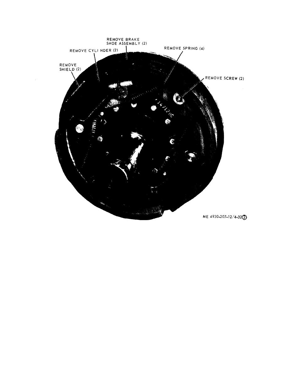
Figure 4-32. Wheel cylinder and brake shoe, removal and installation (sheet 2 of 2)
cone (8, fig. 4-30) and secure with nut (7). Tighten
b. Inspection and Repair.
nut (7) until hub binds on axle spindle, then back off
(1) Inspect brake lines for cracks, bends, kinks
the nut 1/8 turn.
or other damage.
(2) Inspect all threaded areas for damaged
(3) Install lock (6), nut (5), gasket (4), cap (3) and
secure with washers (2) and screws (1).
threads.
(4) Adjust and bleed the brakes (para 4-42).
(3) Inspect brake shoes for excessive wear.
(4) Inspect wheel cylinder for leaks at the rubber
4-44. Hydraulic Master Cylinder
boot.
a. Removal.
(5) Replace all defective parts. Report a defective
wheel cylinder to direct support maintenance.
(1) Release the air brake pressure by opening
drain cock (fig. 3-5) at the air reservoir.
c. Installation.
(2) Remove the master cylinder as illustrated in
(1) Install the brake shoes and wheel cylinders
figure 4-33.
as illustrated in figure 4-32.
(2) Install the wheel and drum assembly, bearing
4-44

