
TM 5-4930-207-34
CHAPTER 3
REPAIR OF ENGINE ACCESSORIES (ELECTRICAL EQUIPMENT)
S e c t i o n I. GENERAL ASSEMBLY
3-1. General
3-2. Generator
The generator assembly has an armature mounted
a. Removal and Disassembly.
at both ends on bearings. The armature rotates
(1) Remove generator assembly and voltage
between pole shoes over which are wound field
regulator as described in TM 5-4930-207-12.
coils. The voltage and current developed in the
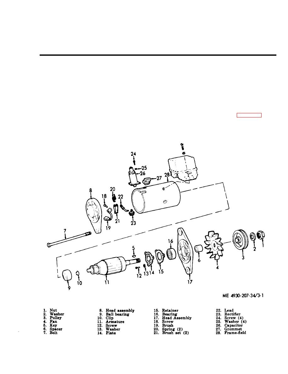
(2) Disassemble the generator assembly in
armature windings is supplied through brushes
numerical sequence as shown in figure 3-1.
riding on a commutator to the generator terminals
and then to the batteries and other electrical
accessories in the circuit.
Figure 3-1. Generator assembly, disassembly and reassembly.
3-1

