
TM
5-4930-207-34
CHAPTER 6
REPAIR OF TRAILER COMPONENTS
S e c t i o n I. SERVICE BRAKES
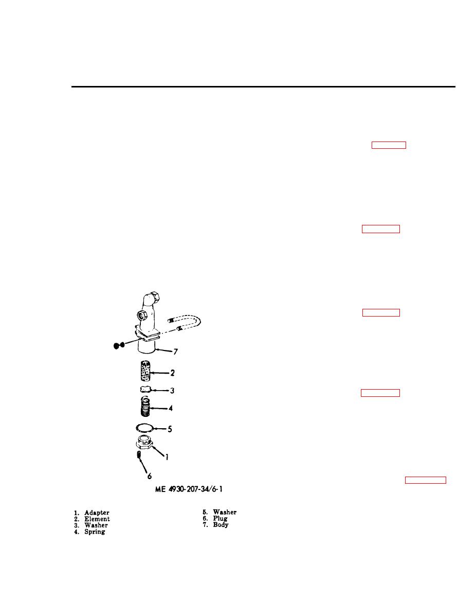
to trailer frame. Remove other air filter in a
6-1. General
similar manner.
The trailer service brakes are the scavenger type
actuated by a diaphragm-type air chamber. Each
assembly of air filter in numerical sequence.
brake has two wheel cylinders secured to the
c. Inspection.
backing plate. The wheel cylinders are actuated
(1) Inspect filter body for cracks, breaks,
hydraulically to give an equal pressure to all
stripped threads, and other damage.
brakeshoes. The air relay valve controls the trailer
(2) Inspect spring for distortion or fatigue.
brakes and automatically applies the trailer brakes
d. Repair.
in event the trailer separates from the towing
(1) Repair is made by replacement.
vehicle.
(2) Replace parts supplied in kit.
e. Reassembly. Refer to figure 6-1 and reassem-
6 - 2 . Air Filters
ble the air filter in reverse of removal.
a. Removal. Disconnect two lines from air fil-
f. Installation. Refer to TM 5-4930-207-12 for
ter, remove two nuts and U-bolt holding air filter
correct installation of air filter.
6-3. Hydraulic Master Cylinder
a. Removal. TM 5-4930-207-12 provides re-
m o v a l instructions for the hydraulic master
cylinder.
semble the hydraulic master cylinder in numerical
sequence,
c. Inspection.
(1) Inspect body for dents, stripped threads,
and other damage.
(2) Inspect spring for distortion or fatigue.
d. Repair. Replace defective parts.
e. Reassemble. Refer to figure 6-2 and reas-
semble the hydraulic master cylinder.
f. Installation. Refer to TM 5-4930-207-12 and
install the hydraulic master cylinder.
6-4. Brakeshoes and Linings
a. Removal. Refer to TM 5-4930-207-12 and
remove the brakeshoes.
b. Disassembly. Disassemble the brakeshoe as
illustrated in numerical sequence in figure 6-3.
c. Inspection.
(1) Inspect the brakeshoes for cracks and
breaks.
(2) Inspect linings for wear and evidence
of grease or hydraulic fluid having penetrated the
linings.
Figure 6-1. Air filter, disassembly and reassembly.
6-1

