
TM
5-4930-207-34
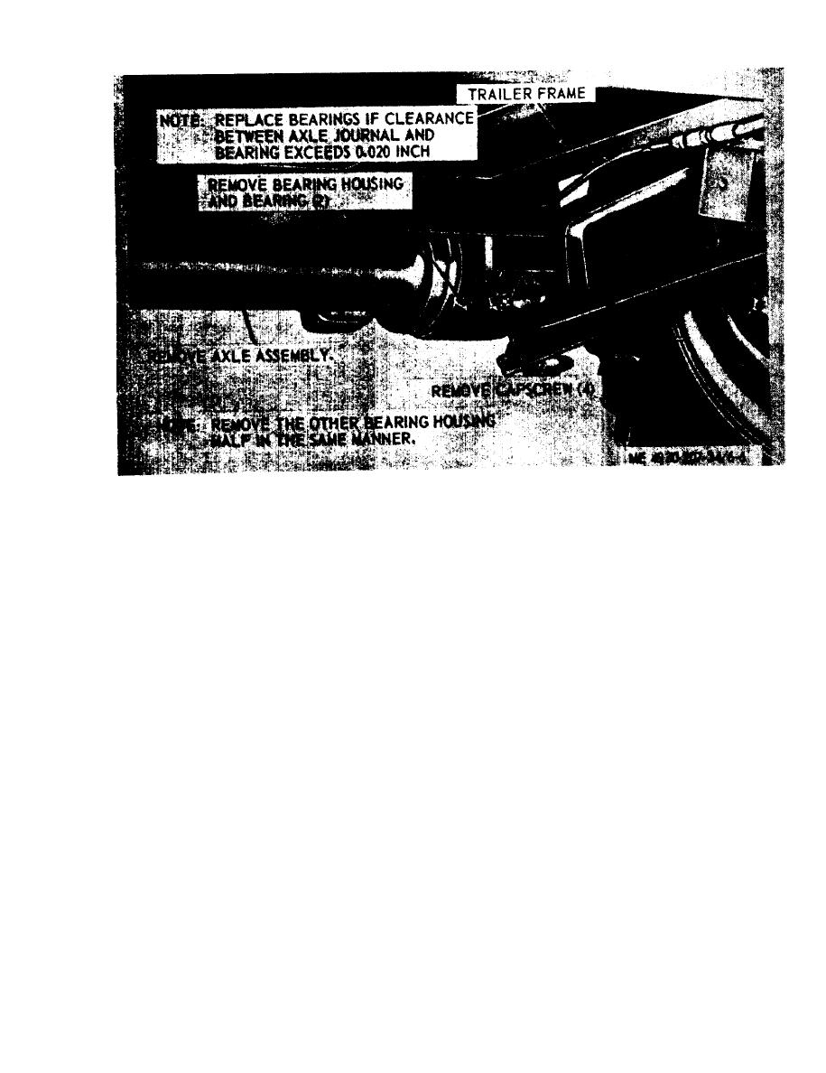
Figure 6-6. Axle assembly, removal and installation.
S e c t i o n Ill. TRAILER FRAME
(5) Brakes and wheel cylinders,
6-9. General
(6) Brake valve.
The trailer frame is an all steel-welded construc-
(7) Air reservoir.
tion consisting of two parallel frame rails with
(8) Landing gear.
crossmembers between the rails. The frame has
a landing gear bracket, spring hanger bracket,
(9) Shock absorber.
hand lifting bars, lashing rings, and two upper
(10) Springs
halves of the bearing housing welded to it.
(11) Axle assembly
b. Inspection and Repair.
6-10. Trailer Frame
(1) Inspect trailer frame for cracks, breaks,
a. Removal. Refer to TM 5-4930-207-12 to
broken welds, and other damage.
remove items as follows:
( 2 ) Straighten minor bends and reweld
(1) Reflectors, clearance lights, taillights,
broken welds. Replace a frame which is damaged
and blackout lights.
beyond repair.
(2) Lunette
c. Installation. Install in reverse order of re-
(3) Brake hydraulic system tubing.
moval. Refer to TM 5-4930-207-12,
(4) Brake air system tubing.
6-5

