
b. Installation. Installation is the reverse of
(2) Remove the spring (para 3-85).
removal.
(3) Remove the brake assemblies (para
3-76).
5-24. Trailer Frame
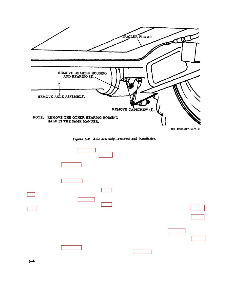
(4) Refer to figure 5-2 and remove the
a. General. The trailer frame is an all-steel-
axle assembly.
welded construction consisting of two parallel
c. Installation.
frame rails with cross-members between the
(1) Refer to figure 5-2 and install the
rails. The frame has a landing gear bracket
axle assembly.
spring hanger bracket, hand lifting bars,
(2) Install the brake assemblies (para
lashing rings and two upper halves of the bear-
3-76) .
ing housing welded to it.
(3) Install the springs (para 3-85).
b. Removal and Disassembly.
(4) Install the shock absorbers (para
(1) Remove the enclosure assembly (para
3-37).
(2) Remove the battery drawer (para
5-23. Air Tank Receiver
3-38) .
a. Removal.
(3) Remove the toolbox, trouble light
(1) Drain off air pressure that may exist
reel and fuel filler assembly (para 3-39).
in the air tank receiver.
(4) Remove the engine assembly (para
(2) Disconnect all lines connected to the
3-41).
air tank receiver.
(5) Remove the trailer blackout stop and
(3) Refer to figure 5-3 and remove the
taillight (para 3-64).
air tank receiver.

