
11. Slowdown Assembly
a. Location. The slowdown assembly is located on the crank-case cover next to the engine governor.
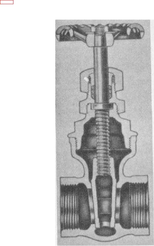
Figure 9. Receiver service valves.
b. Purpose. The slowdown assembly is merely a plunger within a barrel, which provides an engine idle condition
during the unloading cycle. During the unloading operation, air pressure from the unloader pilot valve pushes out the
plunger against the governor lever to change engine speed to a slow idle. When air pressure is removed, the plunger is
backed into the barrel by the governor lever spring to increase the engine speed.
20

