
(10) and valve rotators (11) and compress each spring until the spring lock retainers (12) can be slipped into
the groove around the valve stem.
(2) Make certain that an expansion plug (27) is pressed into each end of the rocker arm shaft (15). Press a
spring retainer (26) into the groove at one end of the rocker arm shaft and, in the order listed, install the
following rocker arm parts: end spring (25), rocker arm assembly (5), rocker arm bracket (8), rocker arm
assembly (5), spacer spring (9), a second pair of arms (5) with a bracket (8) between, spacer spring (9), a
third pair of arms (5) with bracket (8) between, spacer spring (9), a fourth pair of arms (5) with bracket (8)
between, and another end spring (25). Compress these parts until the remaining spring retainer (26) can be
installed.
e. Installation (fig. 57).
(1) Apply a light coat of general purpose grease on the crankcase mounting surface and upper surface of the
cylinder head gasket (18), and install the gasket.
(2) Lift the assembled cylinder head into position over the top of the crankcase, and very carefully lower the
head down over the mounting studs and onto the gasket. Insert the eight push rods (24) down into the rod
openings behind the rocker arm bracket mounting studs.
(3) Rotate the rocker arm brackets (8) until the stud hole in each bracket is alined with the corresponding hole
in the rocker arm shaft (15). Drop a : y8-inch or 7/16 inch bolt down into each mounting hole to keep these
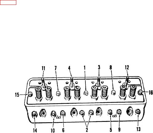
Figure 58. Engine cylinder-head stud nut tightening diagram.
132

