
Rotate the crankshaft if necessary. Install the bearing caps (1) with their bearing shells. Tighten the connecting rod bolt
nuts to 90 foot-pounds of torque.
224. Camshaft and Gear
a. Removal. Remove the fuel pump (par. 75a). Remove the crankcase covers (par. 216a). Remove the gear cover
(par. 220a). Remove the engine cylinder head and valves (par. 122a) and lift up and tie the valve tappets (16, fig. 106)
so they will not catch the cams on the camshaft (3, fig. 105). Turn the engine so the timing marks on the camshaft gear
(2) and crankshaft gear (6, fig. 103) coincide. Note this position. Pull the camshaft and gear from the crankcase. Twist
the gear to disengage it while pulling. Do not remove the cup plugs (1 and 4, fig. 105).
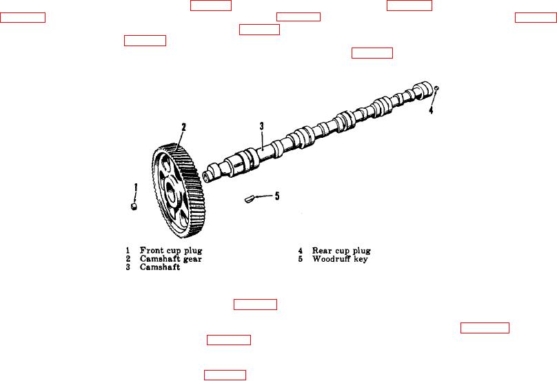
Figure 105. Exploded view of camshaft and gear.
b. Inspection. Inspect the camshaft gear (2, fig. 105) for chipped or broken teeth. Examine the camshaft (3) for
scratches or obvious wear. Slight scratches can be removed with crocus cloth. Clean any residue from the 'camshaft
surface. If the gear is damaged, pull it off over the Woodruff key (5) using a gear and bearing puller (par. 179). Carefully
press on the new gear with an arbor press (par. 179). If the camshaft is damaged beyond repair, replace the camshaft
and gear as a unit. The camshaft and front cup plug (1) are not serviced separately.
c. Installation. Insert the camshaft (3, fig. 105) and camshaft gear (2) in the front of the crankcase. Be careful in
meshing the gears. See that the timing marks on the camshaft and
239

