TM9-4310-396-13
a.
Test Engine Generator. - continued
(1) Engine generator voltage test. - continued
(c) Set volt/ammeter to the 100 VAC range.
(d) Start engine and check volt/ammeter.
(e) When volt/ammeter reads the specified value, engine generator is in normal operation. (Measure
voltage between the connectors.)
(f)
Refer to Table 5-3 Voltage (VAC) for generator value.
Table 5-3 Voltage (VAC)
Engine
VAC Range
Comments
3750 rpm
Approx. 53.8
If the voltage is too low or over voltage, the magnet is
demagnetized or disconnected.
3200 rpm
Approx. 46.0
(2) Engine generator stator coil continuity test.
(a) Remove intake air cleaner (reference para. 4-17).
(b) Remove recoil starter (reference para. 4-18).
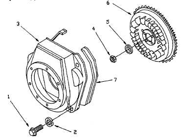
(c) Remove cap screws (1, Figure 5-5), lock washers (2), and cooling fan case (3).
(d) Remove plain hexagon nut (4) and flat washer (5).
(e) Remove flvwheel (6).
Figure 5-5. Cooling Fan Case and Flywheel.
5-12