TM 9-4310-397-14
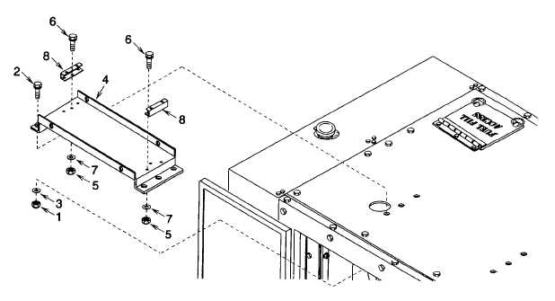
Figure 4-12. Riser Assembly
(6)
Remove four self locking nuts (5), hex washer head bolts (6), flat washers (7), and channel mountings (8).
Discard self locking nuts.
b.
Installation.
(1)
Install channel mountings (Figure 4-12, 8) onto riser (4) using four hex washer head bolts (6), flat washers
(7) and new self locking nuts (5) (item 3, appendix H).
(2)
Aline riser (4) onto cover and secure using six hex washer head bolts (2), flat washers (3), and new self
locking nuts (1) (item 3, appendix H).
(3)
Install exhaust pipes and muffler (Figure 4-11).
(a)
Install rain cap (4) onto elbow (1).
(b)
Install elbow assembly (1) and exhaust pipe (2) on muffler (3).
(4)
Install muffler assembly (Figure 4-10, 6) through cabinet opening. Install new gasket (7) (item 2, appendix
H). Secure muffler assembly with clamps (5), hex head screws (4) and tighten.
(5)
Secure muffler assembly to riser by installing two U bolts (2), saddles (3), and four nuts (1).
(6)
Install shroud (Figure 4-9, 4) and secure with four pan head screws (2), flat washers (3), and new self
locking nuts (1) (item 1, appendix H).
(7)
Connect battery cables to batteries. (See para 4-49.)
(8)
Close curbside doors.
4-67