TM 9-4310-397-14
4-58. COMPRESSOR REPLACEMENT. - Continued
(2)
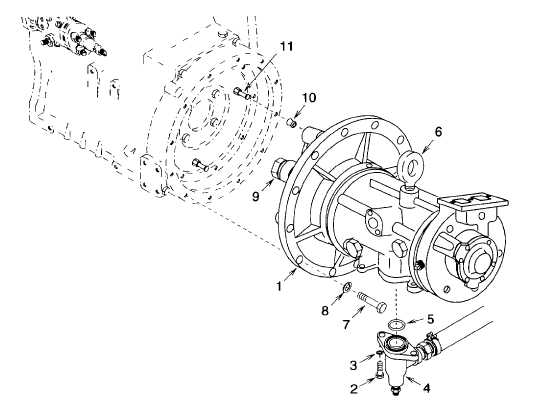
Remove air compressor (Figure 4-61, 1).
(a)
Remove two hex head screws (2), lock washers (3), discharge elbow (4), and preformed packing
(5).Discard preformed packing and lock washers.
WARNING
Removing air compressor by hand can result in personal injury.
CAUTION
Removing the air compressor attaching hardware prior to supporting the air compressor
weight, will allow the air compressor to drop and result in equipment damage.
(b)
Attach lifting device to eye (6) provided on air compressor. Tension should be kept on lifting eye.
(c)
Remove twelve hex head screws (7), and lock washers (8). Discard lock washers.
NOTE
Do not remove bushings and pins unless they are damaged.
(d)
Carefully slide air compressor (1) forward and disengage the coupling (9) from the three bushings (10)
and pins 11)
Figure 4-61. Air Compressor
4-150