TM 9-4310-397-14
5-6. ROCKER ARM COVER REPLACEMENT.
This task covers:
a.
Removal
b.
Installation
INITIAL SETUP
Tools:
Equipment Conditions:
General Mechanics Tool Kit
Battery cables disconnected from batteries.
Item 1, Section III, Appendix B
(See para 4-49.)
a.
Removal.
(1)
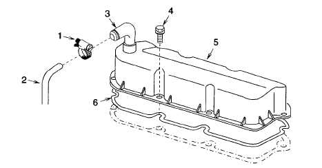
Loosen clamp (Figure 5-16, 1) and remove hose (2) from elbow (3).
Figure 5-16. Rocker Arm Cover
(2)
Remove six washer head screws (4) and remove valve cover (5) and gasket (6). Discard gasket.
(3)
Remove all old gasket or preformed packing material from flange surfaces of valve cover and engine.
b.
Installation.
(1)
Install a new gasket or preformed packing (6) (item 45, appendix H).
NOTE
If engine has been rebuilt and will require break-in it is only necessary to hand tighten a few
cover cap screws. The cover will have to be removed to readjust valves and retorque cylinder
head cap screws after break-in.
(2)
Place valve cover (5) carefully over gasket (6) and secure with six washer head screws, (4). Torque
washer head screws, (4) to 96 in.-lb (10.8 Nm) after break-in.
(3)
Place clamp (1) on hose (2) and secure hose and clamp to elbow (3).
(4)
Connect battery cables per paragraph 4-49.
5-18