TM 9-4310-397-14
(c)
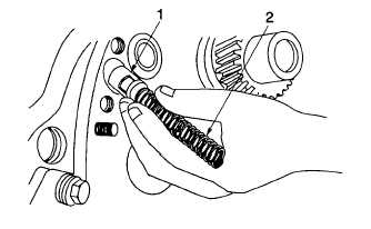
Remove oil by-pass valve (Figure 6-52, 1) and spring (2).
Figure 6-52. Oil By-pass Valve and Spring
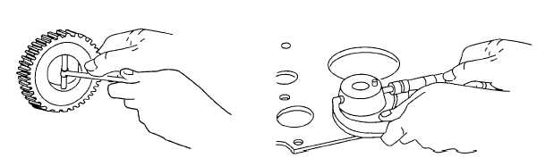
(18) Measure idler gear bushing and shaft (Figure 6-53). Idler gear specifications are as follows:
(a)
New parts dimensions:
1
Bushing ID ......................................................1.751 - 1753 in. (44.94 - 44.54 mm).
2
Shaft OD.........................................................1.750 - 1.751 in. (44.44 - 44.47 mm).
3
Oil Clearance .................................................0.001 - 0.003 in. (0.03 - 0.08 mm).
4
Wear Limit for oil clearance ...........................0.0006 in. (0.14 mm).
(b)
If oil clearance is more that the specification, replace worn parts with new ones.
Figure 6-53. Idler Gear and Bushing
6-47