TM 9-4310-397-14
6-9.
CAMSHAFT. AND TIMING GEAR TRAIN. - Continued
(19) Remove and install idler gear bushings.
(a)
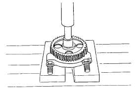
Press worn idler gear bushings out of gears (Figure 6-54).
Figure 6-54. Idler Gear Bushing Removal
NOTE
Upper and lower idler gear bushings have the same ID, but are different.
Bushing with spiral oil groove goes in lower idler gear. Bushing without
groove goes in upper idler gear (pressure lubed). Do not intermix bushings.
(b)
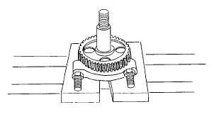
Install correct bushing into respective idler gear using driver (item 17, section III, appendix B) and
handle (item 18, section III, appendix B) (Figure 6-55).
Figure 6-55. Idler Gear Bushing Installation
6-48