TM 9-4310-397-14
6-9. CAMSHAFT, AND TIMING GEAR TRAIN. - Continued
(3)
Clean and inspect timing gear cover.
(a)
Drive crankshaft front oil seal out of cover.
(b)
Remove all old gasket material and sealant from gasket surface on cylinder block and timing gear
cover. If necessary, remove oil filter neck and gasket and injection pump drive gear nut cover plate
and gasket.
CAUTION
Do not allow ball bearings to spin when drying with compressed air.
(c)
Clean cover in solvent and dry with compressed air.
(d)
Inspect cover for cracks or damage. Make sure that seal bore is clean and not nicked.
(4)
Install crankshaft front oil seal.
(a)
Apply a light coating of non-hardening sealant (such as Permatex No. 3) to OD of a new seal. Apply
a light coating of grease to seal lip.
(b)
Support the oil seal bore area of the timing gear cover.
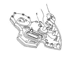
(c)
With timing gear cover removed from block, use Driver (item 20, section III, appendix B) and Handle
(item 18, section III, appendix B) (Figure 6-65, 1) and press oil seal to bottom of bore with spring-
loaded lip facing inward.
Figure 6-65. Oil Seal
(5)
Install timing gear cover.
(a)
Make sure gasket surfaces on cover and front plate are clean.
(b)
Install oil deflector (Figure 6-66, 1) on crankshaft.
6-54