TM 9-4310-397-14
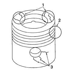
Figure 6-76. Inspect Pistons for Cracks
(1)
Inspect for bent or broken ring lands (2).
(m)
Inspect the inner and outer ends of the piston pin bore for cracks in the skirt (3).
(n)
If the original machining marks are not visible, or the piston skirt is worn to the depth of the original
machining marks, replace both piston and liner.
(o)
If any defects are found, replace the piston and liner as a set. If no defects are found, proceed to next
step.
(p)
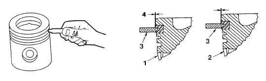
Use the Ring Groove Wear Gauge (3) (item 24, section III, appendix B) to check wear of keystone ring
groove (top groove). Clearance (4) between shoulders of tool and ring land indicate that ring groove is
good. If ring groove is worn, replace piston and liner as a set. If ring groove is good, proceed to next
step.
1 Piston (Figure 6-77, 1) with good keystone ring groove.
2 Piston (2) with worn keystone ring groove.
3 JDE - 62 gauge (3).
4 Tool shoulder-to-ring land clearance (4).
Figure 6-77. Check Keystone Ring Groove
6-63