TM 9-4310-397-14
(f)
When installing new rings from service parts, use a Piston Ring Expander. Install oil ring expander in
bottom ring groove. Position end gap over either end of piston pin.
(g)
Install oil control ring in bottom ring groove over ring expander. Install with end gap on opposite side of
piston from ring expander gap.
(h)
Rectangular compression ring is marked to identify top side of ring. Install rectangular compression ring
in center ring groove with mark toward top of piston.
(i)
Position gap in rectangular compression ring on opposite side of piston from oil control ring gap.
(j)
Keystone compression ring has a mark to identify top side of ring. Install keystone compression ring in
top ring groove with mark toward top of piston.
(k)
Position gap in Keystone compression ring on opposite side of piston from rectangular compression ring
gap.
(l)
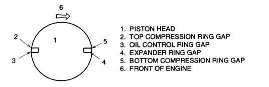
Stagger ring gaps on pistons as shown. If crankshaft was removed, install crankshaft per paragraph 6-11.
Figure 6-91. Ring Gaps
(m)
Coat pistons, liners and inside ring compressor (item 4, section III, appendix B) with oil (item 10, section
II, appendix E).
(n)
Carefully place ring compressor with piston and rod over liner.
CAUTION
Be sure crankshaft journals and liner walls are not damaged when installing
piston and rod in liner.
NOTE
Be sure the word "front" on rod faces toward the front of the engine.
(o)
With piston centered in installing tool and rings staggered correctly, push piston (Figure 6-92, 1) into liner.
6-77