TM 9-4310-397-14
CAUTION
Do not use pneumatic wrench to install main bearing cap screws.
NOTE
Make sure main bearing caps are installed on the bearing bosses from which they
were removed. The numbers stamped on the caps should be on the same side as
the numbers on the block. If there is an arrow on cap, arrow must point toward
camshaft side of block.
(g)
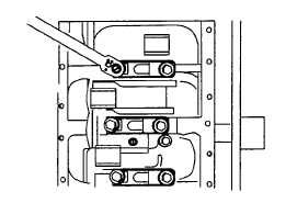
Before tightening cap screws on main bearing caps, align upper and lower thrust flanges on main thrust
bearings. Using a soft-face hammer, tap crankshaft to the rear and then to the front to line up thrust
bearing flanges.
(h)
Torque all cap screws to 85 ft-lb (120 Nm).
Figure 6-109. Install Main Bearings
(i)
Turn crankshaft by hand. If it does not turn easily, disassemble parts and determine the cause.
CAUTION
Using pneumatic wrenches to install cap screws may cause damage to the
threads. Never reuse connecting rod cap screws.
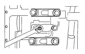
(j)
Install connecting rod caps and bearings. Use new cap screws (item 61, appendix H) and torque to 50 -55
ft-lb (65 - 75 Nm)
Figure 6-110. Install Connecting Rod Caps and Bearings
6-89