TM 5-4310-370-14
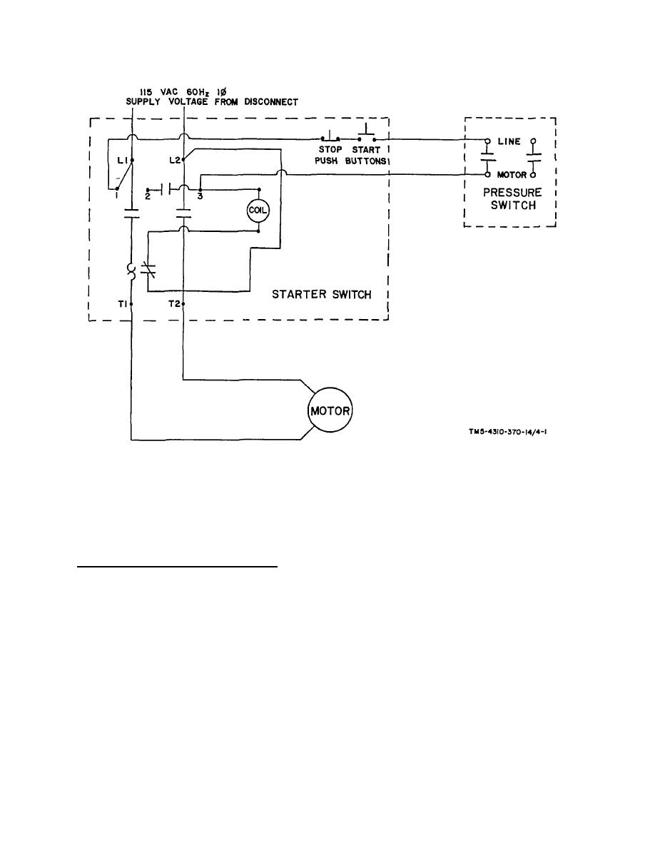
NOTES:
1.
NAMEPLATE ON MOTOR
INDICATES WHICH MOTOR LEADS
SHOULD BE CONNECTED WITH T1
AND T2 FOR PROPER OPERATION.
2.
TERMINALS NO. 1, NO. 2, & NO. 3
ARE CONTROL TERMINALS ON
THE STARTER SWITCH.
TM 5-4310-370-14/4-1
FIGURE 4-1. WIRING DIAGRAM
(4) Pick up unit with forklift of 500 lbs. minimum capacity. Be sure to keep compressor unit level while moving
it.
(5) After compressor unit is placed on vehicle, which is to move it, tie compressor unit down securely and cover
it with a tarpaulin to protect it from elements.
b. Storage of Reciprocating Compressor Unit.
(1) Release air pressure from air receiver and compressor pump before storage of equipment.
(2) Disconnect inflator gage and inflator gage hose and package in same manner as received.
(3) Open air receiver drain and leave it open.
(4) Loosen V belts by loosening motor mounting nuts and push motor towards compressor pump and tighten
motor mounting nuts.
4-2


