TM 5-4310-373-14
NOTE
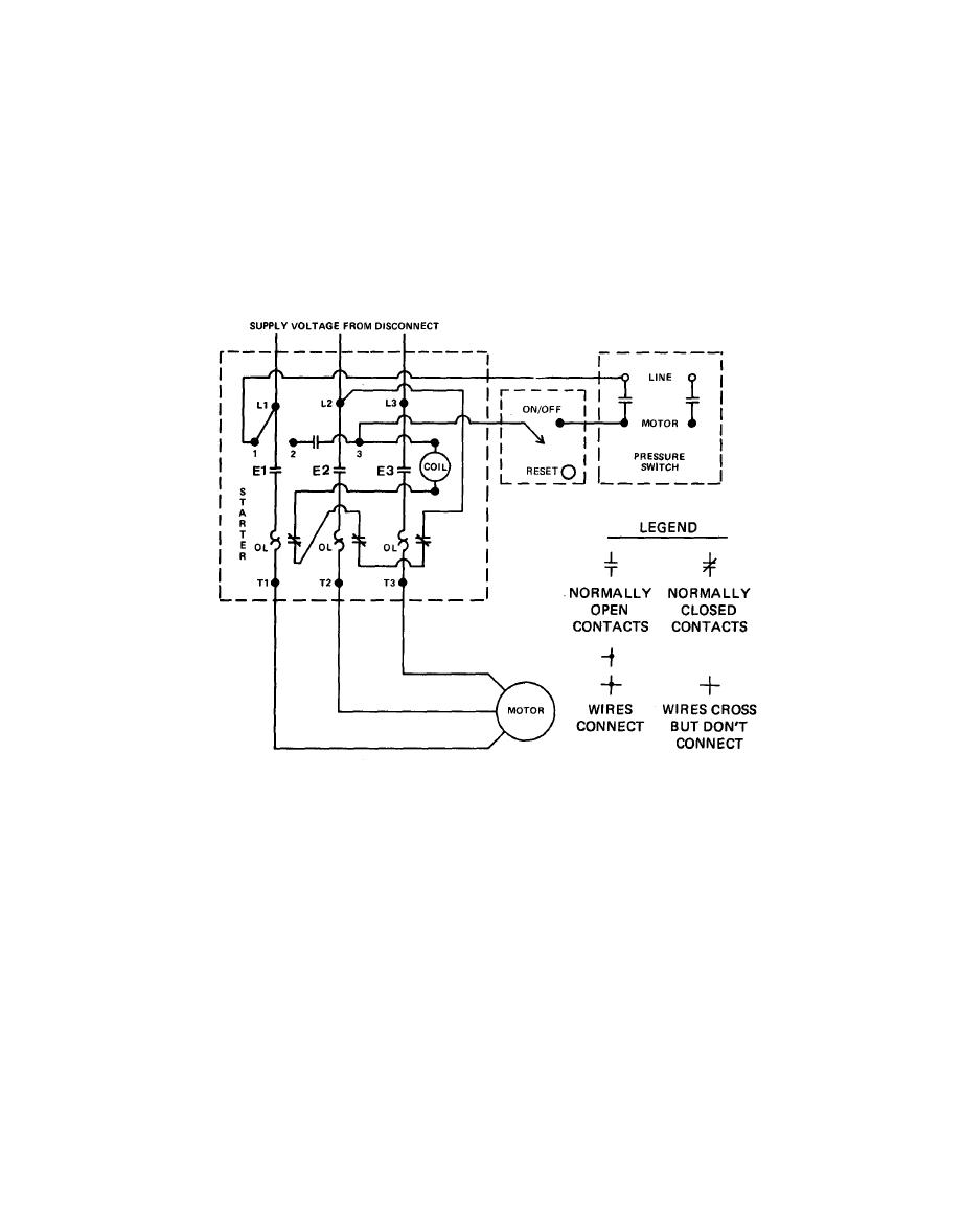
d. ELECTRIC MOTOR CONTROLS. The electric
motor controls consist of the on/off switch,
The overload (OL) in the diagram stands for the
the reset button, the pressure switch, and the
melting alloy or heat type device that opens when
motor starter. These controls make the oper-
too much current is drawn by the motor such as an
ation of the air compressor fully automatic.
OL condition.
Figure 1-5. Electric motor controls schematic
contacts of the pressure switch open and
(1) Power from the main switch comes into
stop the current through the coil. Contacts
the starter at L1, L2, and L3. Connections
E1, E2, and E3 open and the motor stops.
to the motor are at T1, T2, and T3.
(4) Overload condition. If the motor draws
(2) Normal operation pressure below 160 psi.
too much current, overload relay OL heats
When the on/off switch is turned on and
up and the normally closed contacts in
the pressure in the tank is below 160 psi,
series with the coil open up. This stops the
the pressure switch contacts will be closed.
current through the coil and contacts E1,
Current will then go through the coil. The
E2, and E3 open. This stops the motor and
coil then pulls the normally open contacts
prevents it from burning out. The relay
E1, E2, and E3 closed. The circuit to the
has to be manually reset before the motor
motor is completed and the motor starts.
can be started again. This is accomplished
by pushing the reset button which man-
(3) Normal operation pressure above 180 psi.
ually closes the overload relay contacts.
When the pressure goes above 180 psi, the
1-6


