TM 5-4310-375-14
(2) Refer to para 4-30 and install air discharge piping to aftercooler discharge opening.
(3) Refer to para 3-11 and install air intake filter.
(4) Refer to para 4-14 and install drive belts. Adjust belts in accordance with figure 2-3; then, install belt guard.
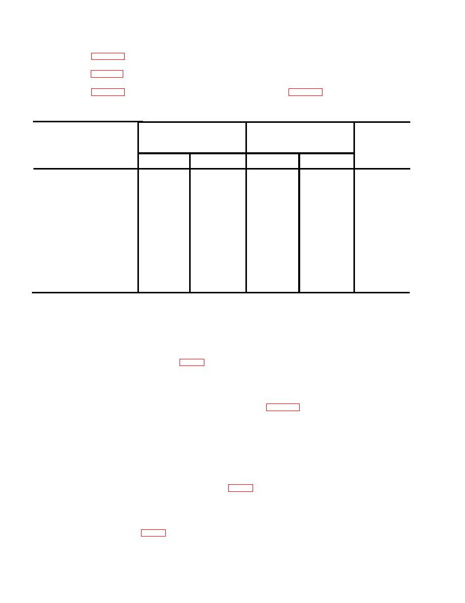
Table 5-2. Compressor Repair and Replacement Standards
MANUFACTURER'S
DIM
MAXIMUM
DESIRED
AND TOL IN INCHES
WEAR OR
COMPONENT
CLEARANCE
AND (MILLIMETERS)
CLEARANCE
MAXIMUM
MAXIMUM
MINIMUM
MINIMUM
First stage cylinder bore
4.1334
4.1350
0.0016
(105.029)
(105.000)
(0.041)
2.0472
2.0488
Second stage cylinder bore
0.0016
(52.040)
(52.000)
(0.041)
1.7699
1.7717
Crankshaft connecting
0.0018
rod insert journal
(45.000)
(44.955)
(0.046)
0.0030
0.0020
0.0015
Connecting rod insert
(0.076)
(0.051)
(0.038)
Intercooler and aftercooler. When notified by organizational maintenance of defective parts detected during their
5-8.
inspection, replace as follows:
Removal/Disassembly. Remove and disassemble the intercooler and aftercooler in sequence below.
a.
(1) Open receiver drain cock to drain receiver pressure; then, close drain cock. Turn main power off at source.
Unscrew and remove three screws (1, fig 5-3), separate intercooler (1) from cylinder head and remove the two
o-ring gaskets (3).
(2) Unscrew and remove six screws (4), separate intercooler cap (5) from intercooler (2) and remove cap gasket (6).
(3) Disconnect air discharge piping from aftercooler (8) air outlet (see para 4-30). Unscrew and remove two screws
(7), separate aftercooler (8) from cylinder head and remove o-ring gasket (9).
(4) Unscrew and remove four screws (10), separate lower aftercooler cap (11) from aftercooler (8) and remove
cap gasket (12).
(5) Unscrew and remove four screws (13), separate upper aftercooler cap (14) from aftercooler (8) and remove
cap gasket (15).
b. Replacement. Replace all damaged gaskets (3, 6, 9, 12, 15, fig 5-3) that are found defective. Replace all parts
that are cracked or broken.
Reassembly/Installation. Reassemble and install intercooler and aftercooler in sequence below.
c.
(1) Assemble cap gasket (15, fig 5-3), upper aftercooler cap (14) and four screws (13) onto aftercooler (8).
5-10


