TM 5-4310-393-14
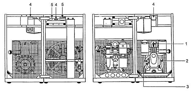
FIGURE 2-1. OPERATOR'S CONTROLS
TABLE 2-1. OPERATOR'S CONTROLS AND INDICATORS
Item
Control or Indicator
Function
1.
Decompression lever
Controls engine decompression. Lever is placed in START position for engine
starting and returns to RUN position when engine reaches operating speed. Place
decompression lever in FREEWHEEL position when freeing engine of compression
to freewheel engine. (Figure 4-3)
2.
Throttle
control
hand
lever
With the hand lever in the START position, the engine is at its highest operating
speed. Speed is varied by moving the lever between START and STOP. Engine
Operating speed for proper air delivery is full throttle.
3.
Extra Fuel Button
Provides more fuel to the engine during cold starting. Pulling the button out allows
more fuel delivery to the engine. Button returns to normal when engine reaches
operating speed.
4.
Hourmeters.
An hourmeter is provided for the compressor section and for the engine section. The
purpose of the hourmeters is to indicate the number of hours of operation for each
unit section.
5.
Pressure gauges.
Pressure gauges are installed in a panel on the air compressor frame. The gauges
have a range of 0 to 7500 psi. They read pressure on the inlet and outlet side of the
pressure maintaining valve.
2-2