
Section III. COOLING SYSTEM
Note. Do not pound or drive on the pump
shaft or carbon seal on shaft will be
a. Removal
damaged.
(1) Remove doors and panel (para 61),
(5) The remaining parts can be lifted off
and housing assembly (para 63).
the shaft
(2) Remove oil cooler (para 124).
b. Cleaning and Inspection.
(3) Remove fan guard (para 76).
(1) Clean the water pump and pulley with
(4) Remove hoses and fittings (para 76).
a cloth dampened with an approved
(5) Remove nuts (26, fig. 25), washers
cleaning solvent and dry thoroughly.
(22) and mounting pads (25).
(2) Inspect the water pump and pulley for
(6) Remove radiator (34).
cracks, breaks, or other damage. In-
b. Cleaning and Inspection.
spect the water pump for evidence of
(1) Clean the exterior of the radiator
c o o l a n t leakage.
(3) Inspect the shaft of the water pump
with an approved cleaning solvent and
for excessive play that would indicate
dry thoroughly. Use a stream of com-
pressed air in the direction opposite
internal wear.
(4) Be sure that the pulley seats tightly on
to normal air flow to clean all dirt
the shaft of the water pump.
from the radiator fins. If necessary,
(5) Replace a defective or damaged water
complete the cleaning with a brush,
taking care not to bend or damage the
pump or pulley.
r a d i a t o r fins.
(6) Inspect all applicable hardware for
(2) Inspect the radiator for bends, cracks,
wear or damaged threads. Replace
damaged fins, possible obstructions,
as necessary.
evidence of leaks, or other damage.
c. Assembly and Installation.
Replace or repair the radiator if it is
(1) Refer to figure 35 for assembly of
damaged.
water pump.
(3) Inspect the hardware for breaks,
(2) Position water pump to front of block
cracks, damaged threads, or other
and secure with lockwashers (5) and
damage and replace if damaged.
nuts (4).
(3) Install fan (para 75).
c. Installation.
(4) Install fan belt and adjust for proper
(1) Position the radiator (34) on the
tension. Secure generator.
chassis.
(2) Secure with mounting pads (25),
washers (22) and nuts (26).
(3) Install hoses and fittings (para 76).
(4) Install fan guard (para 75).
(5) Install oil cooler (para 124).
(6) Install housing assembly (para 63),
and doors and panel (para 61).
a. Removal and Disassembly.
(1) Refer to figure 14 and loosen fan belt
enough to slide over pulley (13, fig.
35).
MEC 4310-247-15/35
(2) Remove fan (para 75).
(3) Remove nuts (4, fig. 35) and lock-
washers (6) holding the pump body
(7) to the front of the block and re-
move the pump assembly.
(4) Remove the impeller (1) with a suit-
able puller.
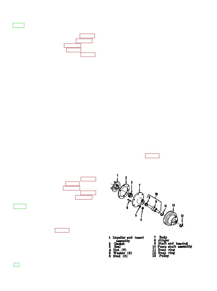
Figure 35. Water pump.
AGO 8166A

