
(13) Install cylinder head cover assembly
(18, fig. 50) and gasket (19). Recon-
nect radiator or heat exchanger outlet
hose.
a. Removal and Disassembly. Remove and
disassemble the internal parts of the engine as
shown in figure 57.
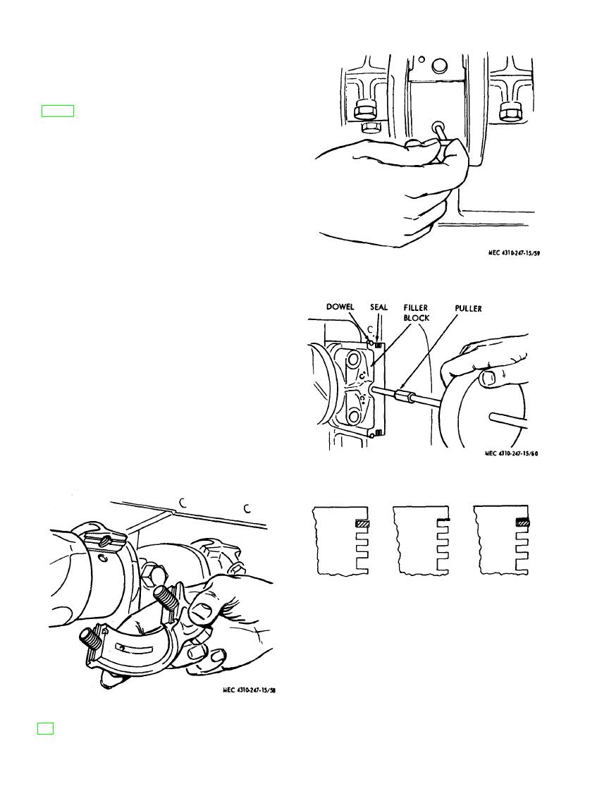
(1) Refer to figure 58 and remove con-
necting rod cap (36, fig. 57). Remove
the screws (30) and washers (26)
holding the cap to the rod.
Note. Keep the caps and screws in nu-
merical order so that when the pistons and
rods are removed from the engine, the cap
can be reassembled and kept with its mating
part.
Figure 59. Crankshaft bearing removal.
(2) Push the piston (45, fig. 57) and con-
necting rod (36) up through the top
of the cylinder.
(3) Remove the remaining three pistons
and connecting rods in the same man-
ner.
(4) Remove starting jaw (8) and washer
(9) and remove the crankshaft pulley
(10) with a puller.
(5) Remove the screws holding gear cover
to the front of the block and those
holding the injection pump drive hous-
ing to the gear cover.
(6) Remove the oil pump suction tube.
(7) Remove each main bearing cap (22,
27, and 32).
Figure
60.
Filler
block
removal.
RESTORED
REMACHINED
WORN RING
RING GROOVE
GROOVE, WITH
GROOVE
INSERT
MEC 4310-267-15/61
Figure 61. Ring groove insert installation.
(8) Remove crankshaft bearings (23, 29,
and 33). Figure 59 shows how to re-
move upper half of bearings.
(9) Remove filler block assembly, then tilt
forward to clear the engine housing
Figure 58. Connection rod cap removal.
AGO 8166A

