
TM 5-4310-276-14
Table 4-2. Troubleshooting (cont)
Malfunction
Test or Inspection
Corrective Action
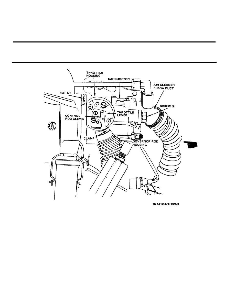
(2) Remove two screws and remove the front throttle housing cover and gasket.
(3) Spread control rod clevis from throttle level.
(4) Remove screw and disconnect throttle level from shaft.
(5) Remove clamp from governor rod housing hose.
(6) Remove the fuel line to the carburetor.
(7) Remove two screws and remove the air cleaner elbow duct from carburetor.
(8) Remove two carburetor mounting nuts and remove the carburetor and gasket from the in.
take manifold. Discard the gasket.
(9) Remove two screws and remove the throttle housing from carburetor. Remove rear cover
and gaskets from the throttle housing.
b. Cleaning and inspection.
WARNING
Drycleaning solvent, P-D-680, used to clean parts is potentially dangerous to per-
sonnel and property. Avoid repeated and prolonged skin contact. Do not use near
open flame or excessive heat. Flash point of solvent is 100F (38C).
4-10
Change 3

