
TM 5-4310-349-14
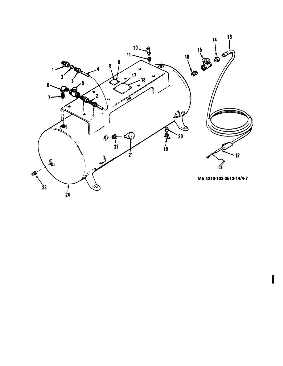
13.
Air hose assembly
1.
Body, compression fitting
14.
Bushing, pipe
2.
Ferrule, compression fitting
15.
Valve, globe
3.
Nut, compression fitting
16.
Nipple, pipe
4.
Tube, exhaust
17.
Screw, drive
5.
Valve, check
18.
Plate
6.
Elbow, street
19.
Cock, drain
7.
Nipple, pipe
20.
Bushing, pipe
8.
Screw, drive
21.
Gage, pressure
9.
Plate
22.
Bushing, pipe
10.
Valve, safety
23.
Plug, pipe
11.
Bushing, pipe
24.
Air receiver
12.
Gage, inflator
Figure 4-7. Air receiver, lines and fittings, model HR10-8M-1 or HR10-8M-4
Change 2 4-11

