Home
Download PDF
Order CD-ROM
Order in Print
Figure 4-7.1. Air receiver, lines and fittings, model 20-277M
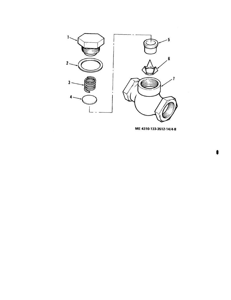
Figure 4-8.1. Check valve assembly, model 20-277M
TM-5-4310-349-14 Compressor Air; Tank-Mounted; Electric Motor Driven 25CFM AT 175 PSI Champion Model No. HR10-8M-1 and HR10-8M-4 Manual
Page Navigation
27
28
29
30
31
32
33
34
35
36
37
TM
5-4310-349-14
1.
Cap
3.
Spring
5.
Seat
7.
Body
2.
Gasket
4.
Disc
6.
Guide
Figure
4-8.
Check
valve
assembly,
exploded
view,
model
HR10-8M-1
or
HR10-8M-4
Change
2
4-13