
TM 5-4310-369-14
Section III. OPERATION UNDER NORMAL CONDITIONS
Wind starter rope clockwise around starter
(7)
Operating Procedure
pulley (6).
a. General. The operator must know how to perform
With a quick, steady pull, start the engine.
(8)
every operation of which the air compressor is capable.
When engine starts, gradually open choke
(9)
This section gives instructions on starting and stopping the
lever (5).
air compressor, basic motions of the air compressor, and on
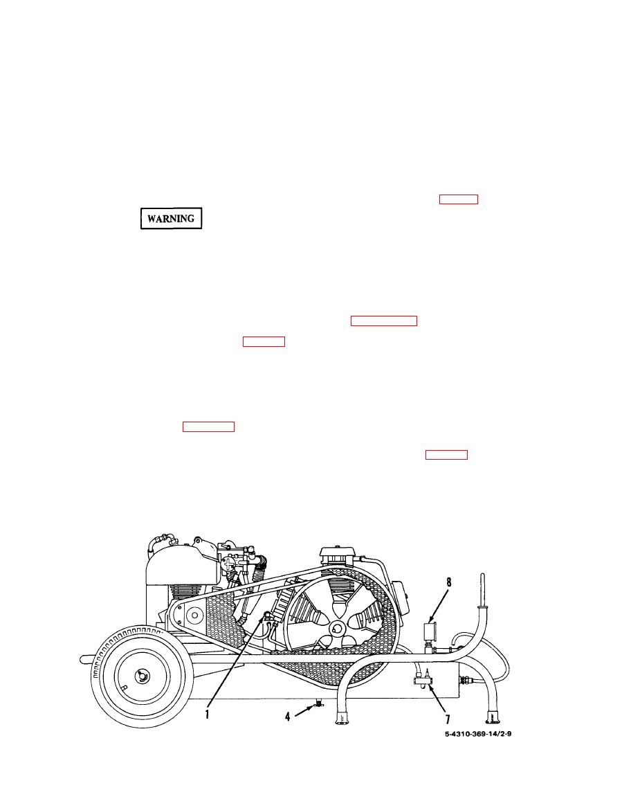
Place release valve lever (7) in closed position.
(10).
coordinating basic motions to perform specific tasks for
(11) Close draincock (4).
which the equipment is designed. Since nearly every job
(12) Perform the necessary During Operation Pre-
presents a different problem, the operator may have to
ventive Service as indicated in table 2-1.
vary given procedures to fit the individual job.
(13) Watch for any unusual noise or vibration.
d. Operation.
(1) Perform starting steps 1 through 12.
Operation of this equipment presents a noise
hazard to personnel in the area. The noise
between 140 to 175 psi (9.8 to 12.3 kg/sq cm).
level exceeds the allowable limits for unpro-
(3) Unloader valve (7) is set to unload at 175 psi
tected personnel. Wear ear muffs or earplugs
(12.3 kg/sq cm). Check adjustment and replace valve if
which were fitted by a trained professional.
valve does not unload at between 170 and 180 psi. Initial
Do not use this compressor for charging
adjustment will be necessary when installing a new valve.
cylinders that require breathable air.
Refer to paragraph 4-17.
b. Preparation for Starting. Perform the Preventive
e. Stopping.
Maintenance Checks and Services as indicated in table 2-1.
(1) Turn ignition switch (3) off.
c. Startng.
(2) Depress handle on airhose inflation assembly
(1) Turn fuel shut-off valve (1) on and position
until air pressure gage on tank reads 30 psi or less.
3-way fuel tank selector valve to unit tank or auxiliary tank.
(3) Open draincock (4) to blow remaining air and
(2) Open fuel tank vent valve (2).
condensate from tank.
(3) Turn ignition switch (3) on.
(4) Close draincock.
(4) Open draincock (4), air.
(5) Turn fuel shut-off valve off (1).
(6) Close fuel tank vent valve.
(6) Depress handle on airhose inflator assembly to
(7) Perform the necessary After Operation Preven-
unload compressor.
tive Services as indicated in table 2-1.
NOTE
The compressor is unloaded when the tank air
pressure gage reads 0 psi.
-

