TM 5-4310-384-13
SECTION III. TECHNICAL PRINCIPLES OF OPERATION
1-13.
GENERAL. This section contains a description of how the air compressor works. The overall system was
described in paragraph 1-9. The operation of the compressor unit is described in further detail in paragraph 1-14, and
operation of the electric motor is described in paragraph 1-15, and electric motor controls are described in paragraph
1-16.
1-14.
OPERATION OF THE AIR COMPRESSOR UNIT.
a.
The air compressor is a two stage air cooled type compressor powered by the electric motor through pulley,
belts and flywheel. The air compressor has two low pressure cylinders which both feed into the high pressure cylinder.
Only one low pressure cylinder is shown in the illustration.
b.
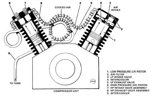
The cycle starts with the low pressure piston (1) at the top of its stroke. When the piston moves down, it draws
air through the air filter and silencer (2)and inlet valve blade (3) into the cylinder. The air filter keeps dirt out of the
cylinder head.
c.
On the upstroke, inlet valve blade (3) closes and the low pressure piston (1) pushes air out into the intercooler
(4) through the exhaust valve blade (5). Compressing the air heats it up. The finned intercooler tubing (4) gets rid of
some of that heat before passing the air on to the high pressure head. The intercooler is cooled by air drawn by the
flywheel fan blades.
d.
The high pressure stage works the same as the low pressure stage except that the high pressure piston (6)
goes up when the low pressure piston (1) goes down. The low pressure piston draws air in while the high pressure piston
pushes air out.
e.
Compressed air in the high pressure cylinder enters through intake valve assembly (7) and exits (at high
pressure) through the exhaust valve assembly (8) to the aftercooler (9).
f.
The aftercooler tubing (9) is looped around the back of the compressor to allow air cooling from flywheel fan
blades. Air passes from the aftercooler through a check valve to the air tank.
Operation of Compressor Unit
1-8