TM 5-4310-384-13
SECTION III. OPERATION UNDER USUAL CONDITIONS
2-5.
PREPARATION FOR USE.
a.
The air compressor is shipped completely assembled, but with the handle assembly removed, secured to a
bottom skid, within a wood crating enclosure. The handle assembly is also shipped within the wood crate, secured to one
side of the enclosure.
b.
Compressor should be placed on a level surface, at least 12" from any wall.
c.
Compressor must be located in a clean, well ventilated dry room so compressor receives an adequate supply of
fresh, clean, cool and dry air. Allow sufficient space around the compressor so that it is accessible from all sides for
maintenance.
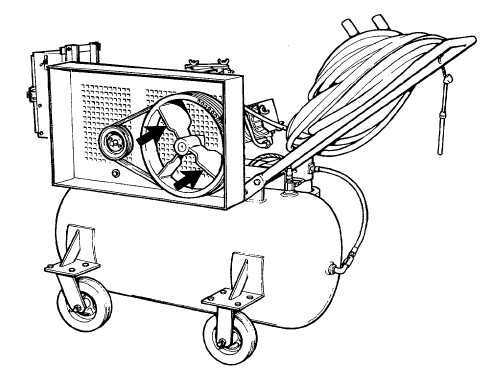
d.
For proper cooling, ensure that no object will obstruct the flow of air through the belt guard to the fan bladed
flywheel.
Proper Air Flow
2-6.
ELECTRICAL CONNECTIONS. Connect the motor starter to single phase power source. The source must
have a separate on/off switch for the compressor.
CAUTION
The electrical components (motor, starter relay and heaters) are factory wired for 230
VAC power source. The components may be rewired for 115 VAC power source. Be
sure these components are wired correctly to match available power source.
2-8