TM-5-4310-389-14
CAUTION
Ensure the bearing shells do not get damaged.
i.
Remove the halves of bearing shells and mark them on the back corresponding to the crankcase. Use an
electric scriber. Remove the lubricating oil filter with base plate. Remove the bearing shell in the middle main
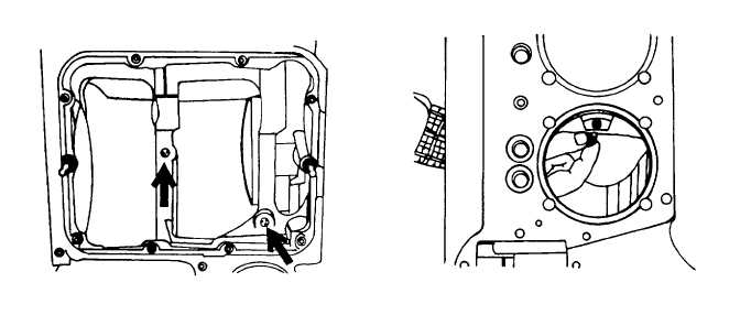
bearing. Unscrew the oil gallery plugs and piston cooling injection nozzles (figures 5-16 and 5-17). Clean all
parts and thoroughly flush all oilways. Do not hot tank.
j.
Remove the crankshaft from the flywheel end of the engine (figure 5-18).
k.
Check all components to determine whether they are suitable for reuse.
l.
Reassembling the Crankshaft Assembly.
NOTE
The bearing must be installed into the front camshaft bearing bore. It is assumed that the bearing is fitted
in the front.
1.
Turn engine upside down.
2.
Determine whether the oil dosing plug is fitted in the oilway of the middle bearing web (figure 5-19, left).
Figure 5-16. Oil Galley Plugs
Figure 5-17. Piston Cooling Injection Nozzles
5-16