TM-5-4310-389-14
29.
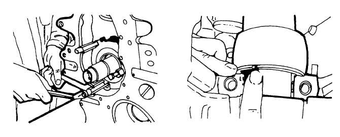
With the aid of tool No.003-0671, press in the front end shield uniformly, without forcing it out of square (figure 5-
30).
30.
Tighten the screws evenly.
31.
Press the crankshaft towards the flywheel end and measure the end clearance on the flywheel side of the middle
bearing web.
32.
The end clearance must be within the range stated in the specifications (table 4-3). If necessary, dismantle the
bearing cap and fit suitable thrust ring halves. With the new thrust ring halves, press out the existing ones at the
bearing web (figure 5-31).
33.
Install the thrust ring halves with the smooth faces to the bearing web or bearing cap. Mount the bearing cap.
Recheck the end clearance of the crankshaft and, if necessary, correct.
34.
Position the balance weights on the crankshaft, taking care that they are in line with the marks. Tighten and lock
down the screws in accordance with torque table H1 (use device No. 003-1102).
NOTE
Engine manufacture recommends new counterweight bolts whenever counterweights are removed.
35.
Install the cover on the under side of the crankcase, with a new gasket held in position with grease, so that the
radial recess faces the screwed plug in the oilway. Assemble the oil drain plug, fitted with a new gasket (figure 5-
32).
Figure 5-30. Pressing in Front End Shield
Figure 5-31. Positioning Thrust Rings
5-21