TM 5-4310-393-14
5-6 3. HAND CRANK ASSEMBLY GEARS.
This task covers. A. Remove B. Inspect C Install
Tools:
Materials/Parts:
Shop Equipment, Automotive
Diesel Fuel NSN 9140-00-286-5294
Maintenance and Repair
Grease, MIL-G-10925 NSN 9150-00-190-0705
Tool Kit, General Mechanic's Set
Grease, MIL-G-21164 NSN 9150- 00-985-7317
Gasket,(3) (PIN 03210000)
Equipment Conditions'
Engine Secured, Removed From Frame
and Placed on a Work Bench
A.
Remove.
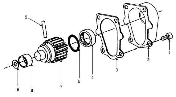
FIGURE 5-13. HAND CRANK ASSEMBLY GEARS
1.
Removing the Gears for Inspection.
a.
Remove four socket head cap screws (Figure 5-13, Item 1) and remove housing (2).
b.
Remove and discard gasket (3)
c.
Remove needle bearing (4), oil seal (5), gear wheel (7) and locking pin (6) as an assembly.
d.
Remove needle bearing (4), oil seal (5), and locking pin (6) from gear wheel (7).
e.
Remove bushing (8) and disk (9).
B.
Inspect
5-15