
(3)
If gap is incorrect, slightly loosen two
c.
Installation.
screws (8), insert screw driver in
(1)
Position the magneto (6) on the unit.
adjusting slot (5) and open or close
(2)
Install one cap screw (2, fig. 22) on
points until proper gap is attained.
the pump side of the magneto (9, fig.
(4)
Tighten the two screws (8), and
recheck the point gap.
(3)
Install one cap screw (4, fig. 21) on
(5)
Install the rotor cap on the cam.
the reel side of the magneto.
(6)
Install the magneto end cap on the
d.
Adjustment.
magneto housing and secure by
(1)
Rotate cam until points (7) are at
installing four screws (8, fig. 20), and
maximum opening. Check gap with
tooth-type lockwashers.
feeler gage.
(7)
Connect the magneto ground cable
(2)
The points should have an opening of
(17) to the magneto cover.
0.015 inch.
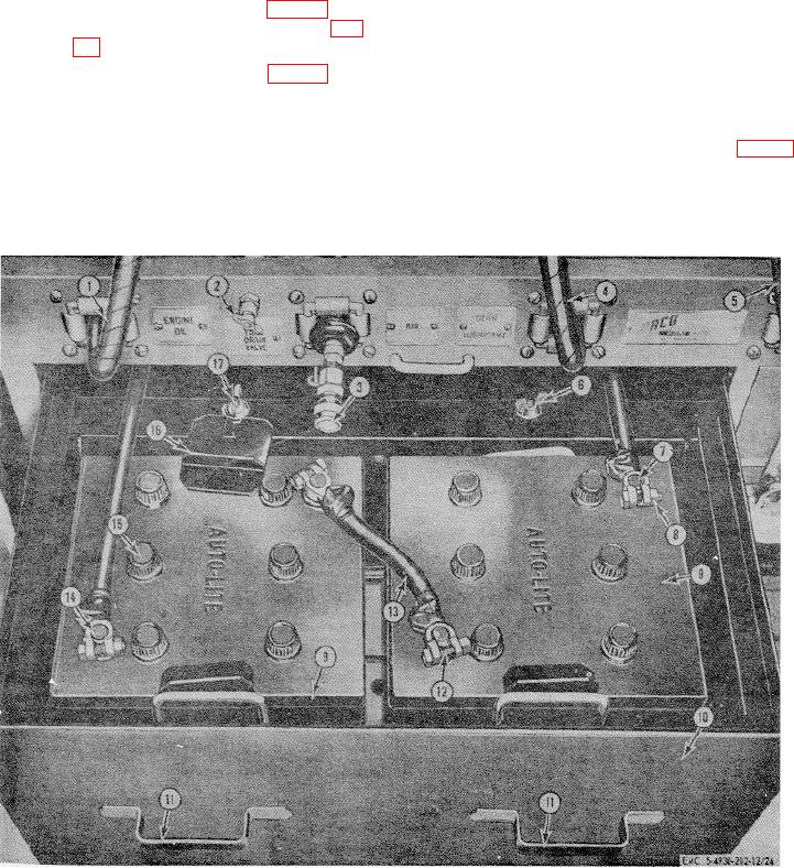
1
Engine oil dispensing line
7
Negative terminal
13
Jumper cable
2
Air tank drain valve
8
Nut, 5/16-18 (4 rqr)
14
Positive terminal
3
Air line coupler
9
Battery
15
Battery filler cap (12 rqr)
4
Gear lubricant dispensing line
10
Battery box
16
Tie-down clamp (4 rqr)
5
Grease GAA dispensing line
11
Battery box handle
17
Tie-down bolt (2 rqr)
6
Wing nut 3/8-16 (2 rqr)
12
Bolt, 5/16-18 x 1 in. Ig (4 rqr)
Figure 24. Servicing batteries.
58

