
1
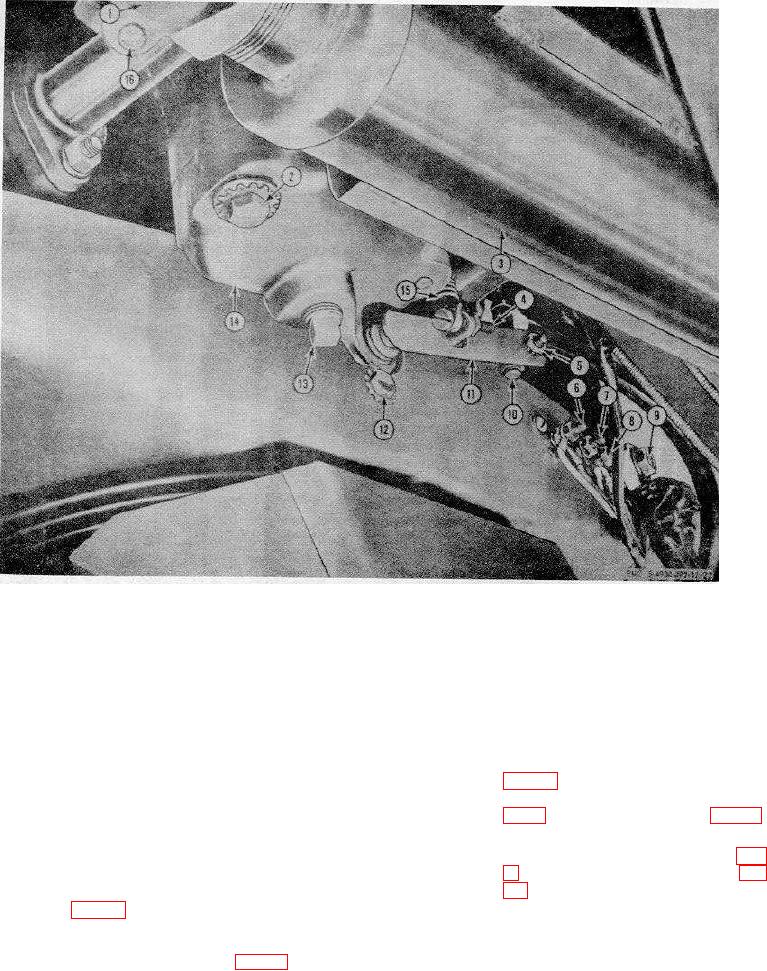
Exhaust pipe
7
Generator terminal F2
12
Screw, ,-20 x in. lg (3 rqr)
2
Cap screw, 3/8-16 x 2 in. Ig (2 rqr)
8
Generator terminal F1
13
Pipe plug, 3/8 in.
3
9
Generator terminal S2
14
Governor
4
Sensitivity adjusting screw
10
Governor linkage
15
Governor spring
5
Nut, No. 10-32
11
Governor arm and shaft
16
Exhaust, pipe bracket
6
Generator terminal A1
Figure 22. Governor controls and magneto removal.
the carburetor fuel line (19) to the fuel
(2)
Disconnect the governor linkage (10,
pump.
fig. 22) from the governor arm and
shaft (11) and from the carburetor (7,
(6)
Inspect the fuel pump for leaks and
proper operation.
from the top of the arm.
112. Governor Controls
(3)
Remove the throttle bracket (14, fig.
a.
Removal.
(1)
Disconnect the governor spring (15,
fig. 22) from the governor arm and
c.
Cleaning, Inspection, and Repair.
shaft (11) by removing the governor
(1)
Inspect the governor arm and shaft,
sensitivity screw (4) and remove the
the governor spring, the throttle
speed adjusting nut (3, fig. 21) from
bracket, and the governor linkage for
the speed stud bracket.
54

