
2-14. Filling Lubricant Tanks
at the alcohol dispenser.
b. Air pressure in the tank will automatically
build up to 175 pounds. This pressure is preset
to cut out at 175 pounds pressure and cut in at
146 pounds pressure.
c. Allow pressure to build until the air re-
ceiver pressure gage (17) shows a reading of
between 150 and 175 pounds air pressure.
d. Remove the transfer pump (21) from its
mounting and install in drum of lubricant to
be dispensed. Heavy grease cannot be pumped;
pack manually.
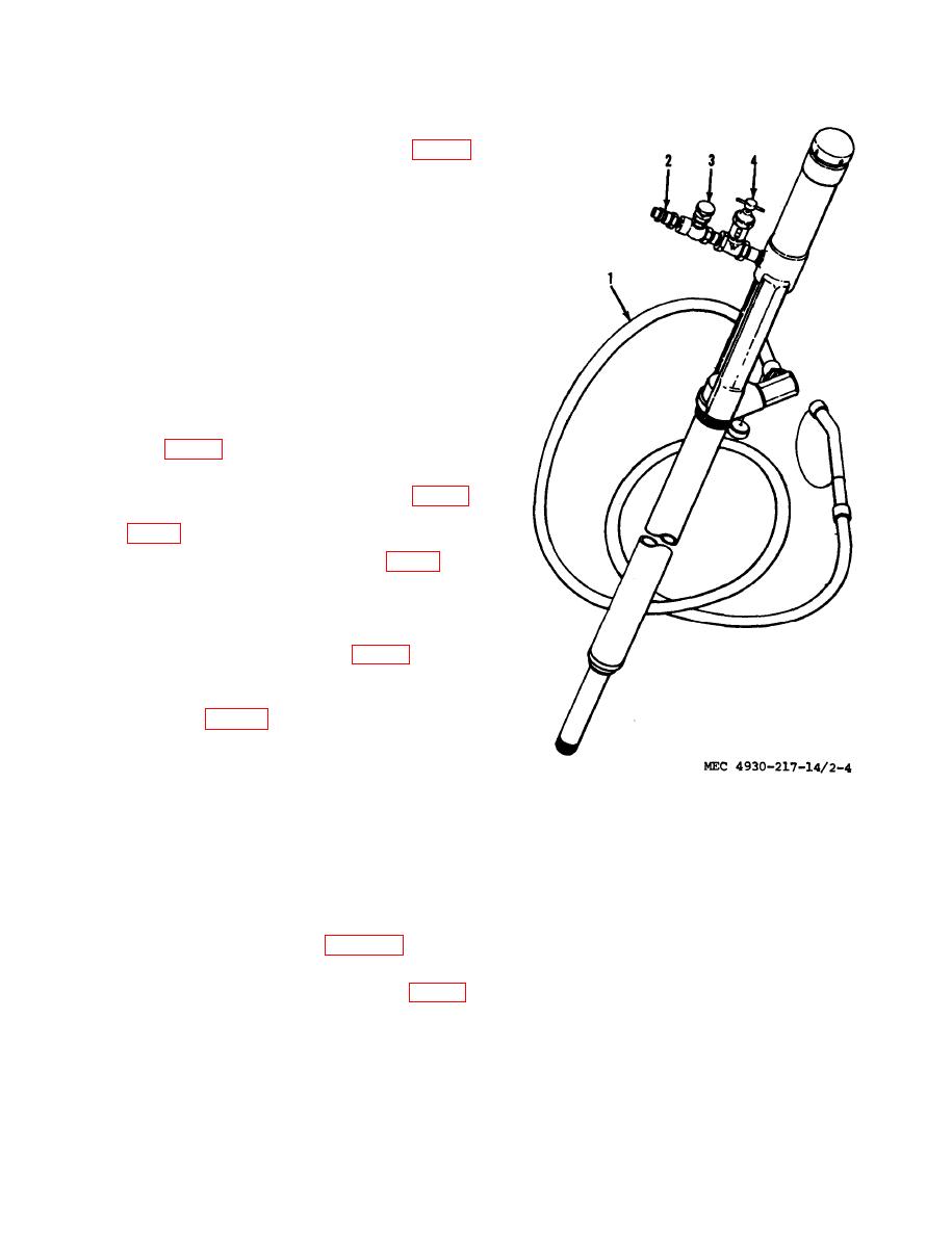
e. Remove the transfer pump hose assembly
(1, fig. 2-4) from the toolbox assembly and
install on the transfer pump assembly.
and attach it to the quick air coupling (2,
insert the transfer hose into the tank to be
filled.
h. Open
the master air valve (50).
transfer pump to the required volume.
j. When the hopper is filled, close master air
valve (50, fig. 2-.3).
Note. Always keep lubricant containers three-quar-
ters full.
Clean and store the transfer pump and
k.
hose in their respective positions.
3 Air valve
1 Hose
l. Open the air tank drain valve (44) to
4 Oiler assembly
2 Quick air coupler
drain moisture and air pressure from the air
tank.
d. Air pressure to each pump must be ad-
justed at the individual pump. Turn the air
ation
regulator handle clockwise to increase air
a. Fill lubricant tanks, (para 2-14 a through
pressure, and counterclockwise to decrease air
c).
pressure. The exact air pressure to operate
pumps must be based on delivery rate required
and close air tank drain valve (44).
and viscosity.
c. Turn the air regulator handles (24) clock-
e. Open the circulating valve (80) of each
wise, until set at the desired air pressure, as
pump by turning the valve handle two full
turns counterclockwise.
registered on the air gauge (25).

