
TM 5-4930-218-14
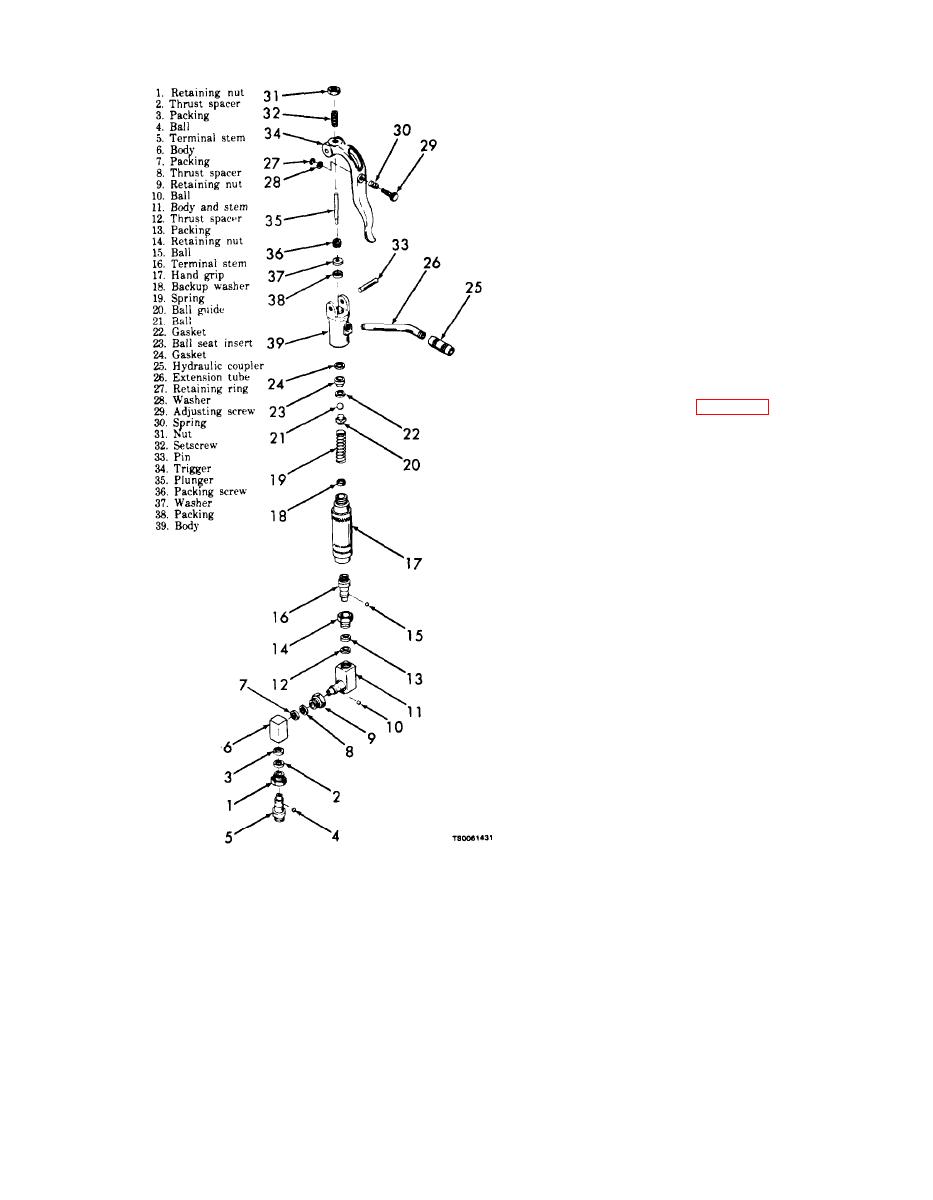
(c) Replace ball seat insert (23) and ball (21).
Clean dispenser thoroughly and reassemble making
sure new gaskets are placed in proper position before
hand grip is replaced.
(3) To replace V-packing (38), proceed as follows:
(a) Place dispenser in vise and unscrew tube
(26) from body (39).
(b) Remove trigger pin (33) and trigger (34).
(c) Unscrew packing screw (36), remove washer
(37), and pull out V-packing (38) with a small hook.
(d) Replace packing, washer, and packing
screw, and install plunger (35).
NOTE
Do not tighten parking screw until plunger has been in-
stalled. The packing screw has a screwdriver slot.
(e) Replace trigger, pin, and tube. Adjust
trigger and dispenser is ready for use.
(4) If further repair or overhaul is required,
disassemble per subparagraph b below.
follows:
(1) Remove the high pressure swivel assembly
(items 1 through 16) from the hand grip (17). You
should not disassemble the high pressure swivel
unless there is evidence of malfunction, If disassem-
bly is required, take care not to lose the balls (4, 10,
and 15) as you remove retaining nuts (1, 9, and 14),
spacers (2, 8, and 12), and packings (3, 7, and 13).
Eight balls are used at each location.
(2) Refer to ball seat insert replacement in-
structions in subparagraph a(2) above and proceed as
instructed to remove items 17 through 24.
(3) Refer to V-packing replacement instructions
in subparagraph a(3) above and proceed as instructed
to remove items 25 through 38.
(4) When necessary, disassemble the trigger (34)
by removing retaining ring (27), washer (28), ad-
justing screw (29), spring (30), nut (31), and setscrew
(32).
c. Cleaning and Inspection.
(1) Clean all parts with dry cleaning solvent (fed.
spec. P-D-680).
(2) Inspect and replace any worn, leaking,
cracked, or damaged parts.
(3) Inspect threaded surfaces for stripped or
cross threads. If beyond repair, replace.
d. Reassembly. Reassembly is essentially the
reverse of disassembly. Note the following
(1) To adjust trigger, loosen lock nut (31) and back
(1) During reassembly you should apply a light
out setscrew (32) approximately one quarter turn or
coating of engine oil on the V-packing and the quad
until handle has 1/2 inch travel,
rings on the trigger pin.
(2) To replace ball seat insert (23) and bail (21),
(2) Do not tighten the packing screw (36) unless
proceed as follows:
the valve stem is inserted, The screw has a
(a) Place dispenser in vise, then unscrew hand
screwdriver slot at the top.
grip (17) from body and remove spring (19).
(3) After reassembly you should test the dispen-
(b) Tap out ball (21), ball guide (20) and ball
ser for correct operation.
seat insert (23).

