TM9-4310-396-13
1-11.5
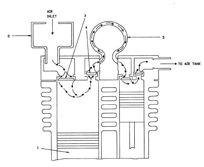
Air Compressor Pump. Figure 1-4 below shows the general operation of the air compressor. The air
compressor has two low pressure cylinders which both feed into the high pressure cylinder. The compression cycle starts
with the low pressure pistons (1, Figure 1-4) at the top of stroke. When the pistons move down, they draw air through the
air filter (2) and inlet valve (3) into the cylinders. The air filter keeps dirt out of the compressor. On the upstroke, inlet
valve (3) closes and the pistons (1) push air out into the intercooler (5) through the exhaust valve (4). Compressing the
air heats it up. The intercooler (5) gets rid of some of that heat before passing the air on to the high pressure stage. The
high pressure stage works the same as the low pressure stage except that the high pressure piston goes up when the low
pressure piston goes down. This way, the low pressure piston is drawing air in while the high pressure piston is pushing
air out. Compressed air from the high pressure stage goes to the air tank through a connecting tube.
Figure 14. Air Compressor Pump Schematic.
1-7