
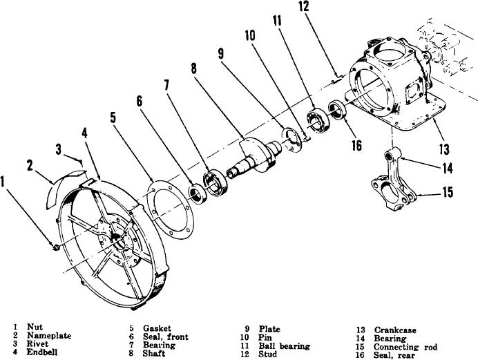
Figure 3-7. Endbell, master rod, and shaft section, exploded view.
d. Assembly.
rod and plate into bearing (11) until it
bottoms. Be certain pin (10) passes
through hole in plate (9).
(1) Using a suitable arbor press, seat
(6)
Press shaft front seal (6) in endbell (4)
shaft seal (17) in counterbore of
counterbore with lip of seal toward
crankcase (13) with lip of seal facing
crankcase side of endbell.
toward fan end of crankcase.
(7)
Press bearing (7) on shaft (8) until it
(2) Press ball bearing (11), smooth side of
bottoms.
inner race up, in bearing counterbore
(8)
Place gasket (5) over installed studs
of crankcase.
(12) and against crankcase (13).
(3) Position connecting rod (15)
with
Position endbell (4) over shaft (8) and
bearing (14) installed, with first stage
press onto bearing (7) until endbell
throw through first stage cylinder bore
bottoms
against
gasket
and
in crankcase. Place pin (10) in shaft
crankcase. Be certain the six holes in
(8) if pin has been removed.
the endbell are aligned with studs (12)
(4) Place plate (9) between connecting rod
before pressing into position.
and bearing (11) with the flat side
(9)
Install six nuts (1) and tighten evenly.
toward connecting rod. Align parts
with inner diameter of bearing.
(5) Press shaft (8) through connecting
26