TM 3-1040-263-34
1
Seal
6
Ball
11
Nameplate
2
Lockwire
7
Piston
12
Seat
3
Cap
8
Preformed packing
13
Spring
4
Spring
9
Nut
14
Preformed packing
5
Retainer
10
Body
15
Fitting
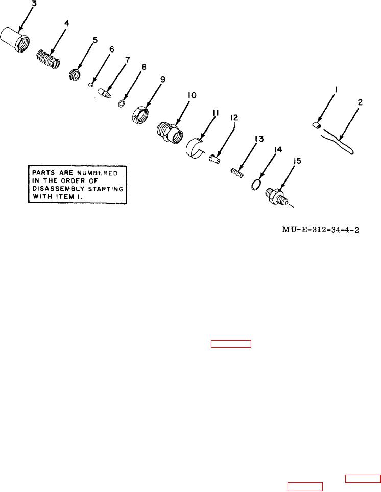
Figure 4-2. High-pressure relief valve-exploded view.
Section II. FAN GROUP
spark plug to prevent accidental starting.
4-4.
General
Using Figure 4-3 as a guide, disassemble the fan guard,
A fan, located in front of the compressor, moves the
and fan and attaching hardware.
cooling air in and around the aftercooler,
heat
exchangers, and compressor. The fan is secured to the
4-6.
Cleaning and Inspection
oil pump shaft and rotates with movement of the shaft. A
metal fan guard channels the air flow and prevents
a. Clean all metallic parts in drycleaning
external interference with the rotation of the fan. General
solvent and air-dry.
support maintenance personnel are authorized to
replace the fan, fan guard, machine bolt, and attaching
b. Inspect all components for nicks, scratches,
hardware
distortion, defective threads, and other damage.
4-5.
Disassembly
c. Check fan (6) for bent blades and the fan
guard (3) for dents that could prevent proper operation.
WARNING
4-7.
Reassembly
Before performing maintenance, disconnect the spark
plug wire from the
Reassembly is the reverse of disassembly (para 4-5).
Torque the machine bolt (4, fig. 4-3) (21 to 23 pound-
feet).
4-3

