
TM 3-1040-263-34
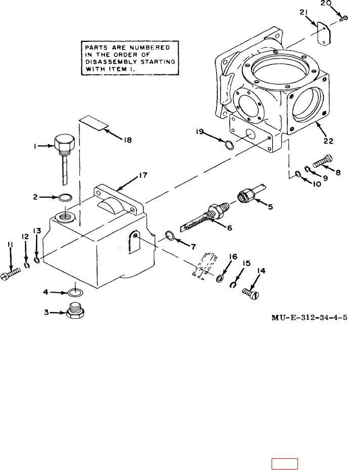
1
Dipstick
8
Screws
16
Washer
2
Preformed packing
9
17
Oil sump
3
Plug
10
Washers
18
Nameplate
4
Preformed packing
11
Screws
19
Quad ring
5
Oil supply tube
12
20
Drive screws
6
Oil strainer
13
Washers
21
Nameplate
7
Preformed packing
14
Screw
22
Crankcase
15
Lockwasher
Figure 4-5. Oil sump and crankcase-exploded view.
against me compressor crankcase. When the pressure
CAUTION
is released, the oil pump assembly will return to its
Drainage to the oil pump assembly and
original position. h. Aline oil pump assembly housing
compressor crankcase can occur if the wave
holes with compressor crankcase holes. i. Assemble
washer is improperly positioned.
three angle brackets (12, fig. 4-4)
g. Check for a properly positioned wave
washer by pressing the oil pump assembly housing
4-9