TM 5-4220-233-14
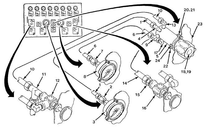
(1) Disconnect tube assembly (1) from adaptor (2) on manifold pressure gauge (3) and from elbow (4) on
inlet gauge port on regulator (5).
(2) Disconnect tube assembly (6) from adaptor (7) on servicing pressure gauge (8) and from elbow (9) on
outlet gauge port on regulator (5).
(3) Disconnect tube assembly (10) from tee fitting (11) on high pressure valve (12) and from elbow (13) on
inlet port on regulator (5).
(4) Disconnect tube assembly (14) from adaptor (15) on servicing valve (16) and from elbow (17) on outlet
port on regulator (5).
(5) Remove button plug from top of handknob (18) on regulator (5).
(6) Remove retaining ring (19) and handknob (18) from regulator (5).
(7) Remove two screws (20) and two lockwashers (21) securing regulator mount bracket (22) and regulator
(5) to control panel (23).
(8) Pull regulator (5) out back side of control panel (23).
(9) Note orientation of mount bracket (22) and distance from bottom edge of regulator (5) to mount bracket
(22).
(10) Loosen two screws (24) and slide mount bracket (22) off of regulator (5).
(11) Note position of four elbows installed on regulator (5) if required.
(12) Remove four elbows from regulator.
b.
Cleaning of Regulator and Removed Components. Refer to Section VII to clean elbows, tube assemblies,
and replacement pressure regulator, as required.
c. Installation
Figure 4-9. Install Pressure Regulator.
(1) Remove button plug from top of handknob (18) on regulator (5) and set aside for later Installation.
(2) Remove retaining ring (19) and handknob (18) from regulator (5) and set aside for later installation.
(3) Apply ante-seizing tape (Item 16, Appendix D) to male pipe threads on four elbows.
(4) Install four elbows onto regulator, as previously noted.
4-31


