TM 5-4220-233-14
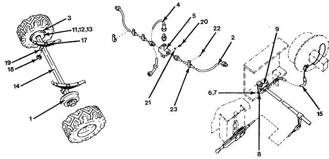
(3) Place container below axle where brake hose (4) connects to "T" fitting (5) and disconnect brake
hose from “T” fitting.
(4) Remove cotter pin (6) washer (7) and clevis pin (8) to release yoke (9) from shaft lever cable
holder.
(5) Loosen jam nuts on cable holder (10) where cable is secured to bracket.
(6) Repeat steps 4 and 5 for other brake cable assembly.
(7) Remove five screws (11), attaching nuts (12) and washers (13) securing brake assembly (1) to axle
(14),then pull brake assembly with brake cable (15) off axle and set aside.
(8) Repeat step 7 for other brake assembly (3).
(9) Position floor jacks under both ends of axle (13) just outboard of springs (15).
(10)
Remove two “U” bolts (17), and four nuts (18), then remove tie plate and stud assembly (19)
from bottom of axle (14).
(11)
Repeat step 10 for other side of axle (14).
(12)
Lower axle (14) using floor jacks and pull out from unit.
(13)
Remove screw (20) and washer (21) securing T" fitting (5) to axle (14).
(14)
Remove four screws (22) and clamps (23) to separate brake lines (2) from axle (14).
(15)
Clean and inspect all removed parts as prescribed in paragraphs 4-15 and 4-16.
b.
Installation.
Figure 52. Install Axle Assembly.
NOTE
When an axle is replaced, both shock absorbers should also be replaced.
5-3


