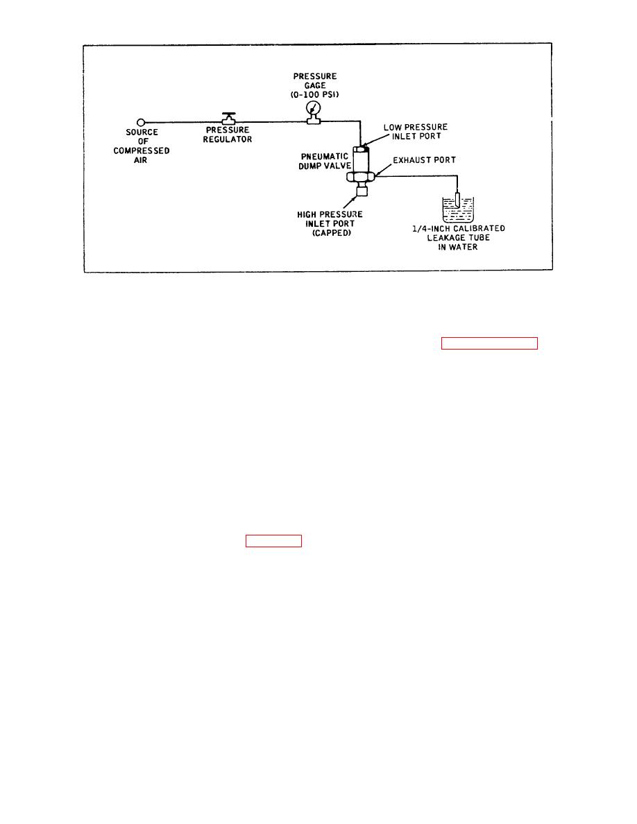
Figure 4-6. Set-up for Testing Pneumatic Dump Valve
4.12.7
INSTALLATION.
Install the filter and
c. If leakage rate exceeds one air bubble per
separator and pneumatic dump valve by performing the
minute, disassemble filter and separator and install new
removal procedure (paragraph 4. 12. 1) in reverse
packing on cap.
sequence. Make sure the pressure relief valve, back
pressure valve and check valve are reinstalled in
4.12.6
PNEUMATIC DUMP VALVE LEAKAGE
accordance with their applicable installation instructions,
TESTS. Test the reassembled pneumatic dump valve
and that all pneumatic connections are leak proof.
as follows before installing the assembly on the filter
Safety wire all parts in accordance with the original
and separator:
equipment configuration.
a. Make test connections to pneumatic dump valve
4.13 DEHYDRATOR ASSEMBLY
as shown schematically in Figure 4-6.
4.13.1
REMOVAL.
Removal of the complete
b. Adjust pressure regulator to apply a pressure of
dehydrator housing assembly should seldom i-e
60 to 65 psig to low pressure inlet port.
required.
However, when necessary, proceed as
c. Leakage from exhaust port shall not exceed
follows:
three cubic centimeters per hour (one air bubble every
two minutes).
a. (See Figure 5-3.) Disconnect dryer to the
connecting tube (31) from elbow (37) installed in bottom
d. Use same test set-up as illustrated in Figure 4-6
(inlet) of dehydrator housing. Loosen nut (40) and
except disconnect leakage tube from exhaust port and
unscrew elbow from port. Remove gasket (38), back-up
connect an adjustable source of high pressure
ring (39) and nut from elbow.
compressed air to high pressure inlet port of pneumatic
dump valve.
b. (See Figure 5-3.) Disconnect dryer-to-filter
connecting tube (41) from union (42) installed at upper
e. With an air pressure of 60 to 65 psig applied to
end of dehydrator housing. Remove union and gasket
low pressure inlet port, apply a gradually increasing air
(43) from port.
pressure to high pressure inlet port. Increase pressure
to 3300 50 psig, then shut-off high pressure air supply.
c. (See Figure 5-10.) Loosen clamps (1) and
remove complete dehydrator assembly from cart frame.
f. Piston in pneumatic dump valve should remain
closed to maintain high Inlet air pressure. When it is
evident that piston is closed, connect a flowmeter to
4.13.2
DISASSEMBLY (See Figure 5-10.)
dump valve exhaust port. Measured leakage shall not
exceed five cubic inches per minute.
a. Unscrew outlet adapter cap (4) from outlet
adapter (8). Remove packing (5), back-up ring (6) and
g. After completing tests, relieve air pressure in
filter disc (7) from cap.
test set-up, disconnect pneumatic dump valve and
install on filter and separator assembly.
35


