TM 5-4310-276-14
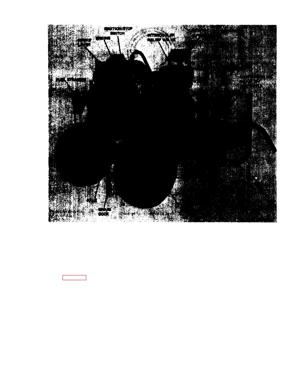
Figure 1-2. Air compressor assembly, left front, three-quarter view.
valves and opens the outlet valves, through which
the air is forced into the intercooler. As the air flows
der, two-stage, air cooled unit. It will deliver 5 cfm
through the intercooler much of the heat of com-
of air at 175 psig to the air receiver tank when belt-
pression is dissipated. The second stage is similar to
driven by the gasoline engine running at a speed of
the first, except the air enters the high pressure cyl-
3,600 rpm (revolutions per minute.) Filtered air as
inder and is recompressed to higher pressure. The
shown in figure 1-3 is drawn into the low pressure
air next flows through the aftercooler where it is
cylinder (the large one) at atmospheric pressure as
cooled before passing into the air receiver tank.
the piston moves down. Air is compressed when the
piston is moving upward, this action closes the inlet
1-3


