TM 5-4310-335-14
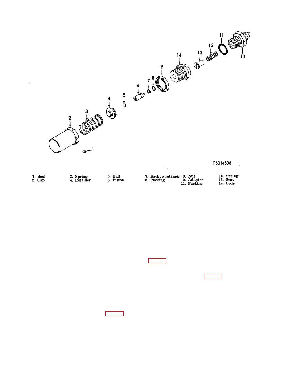
Figure 7-7. Fourth Stage Relief Valve
WARNING
Exercise extreme care when working with high pressure air to prevent injury to
personnel or damage to equipment. Do not attempt to tighten any fitting or
perform any work on equipment when the system is under pressure. Do not
tamper with any pressure relief valves.
(a) Cap pipe thread and retain valve (4). Proof pressure test for 1/2 minute at 160 psi (11.2480
kgs per sq cm) using clean moisture free air or nitrogen. There shall be no audible leakage or visible evidence
of permanent distortion. Relieve the pressure and remove the test cap.
(b) Cap the free tube end of valve body (5, fig. 7-3) and attach a compressed air supply to the
inlet end. Install the valve in a suitable safety fixture.
(c) Adjust the air supply to 100 psi (7.030 kgs per sq cm) and adjust plug (2) until the valve just
starts to pop. If none of the slots in the plug line up with a wire hole in the body (5), (fig. 7-3) turn plug either
way to nearest hole.
(d) Retest by reducing pressure and observe the actual popping pressure which should be 95
(6.6786 kgs per sq cm)-105 psi (7.3815 kgs per sq cm). If it is not, turn plug (2) to the next wire hole to
compensate for possible movement of the plug during valve cycling.
(e) Decrease pressure to 60 psi (4.2180 kgs per sq cm) then increase to 85 psi (5.9755 kgs per
sq cm) and inspect the valve for leakage.
1. Lubricate the threads of plug (2) and body (6) with oil, MIL-L-6085A and assemble the valve in the
reverse order of disassembly.
2. Test the valve as follows:
7-7


