TM 5-4310-335-14
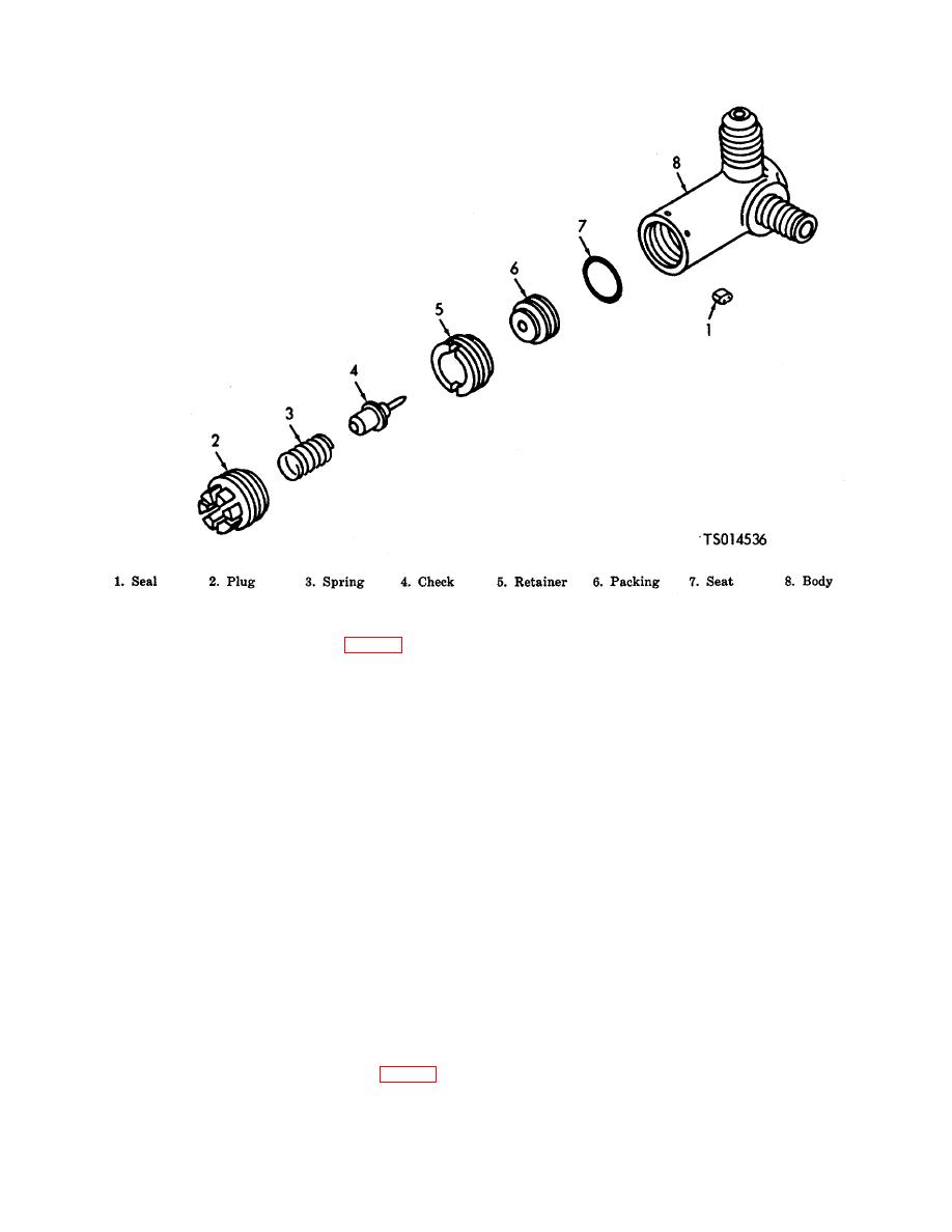
Figure 7-5. Third Stage Relief Valve
(a) Remove cap seal (1, fig. 7-7).
(b) Remove cap (2), helical spring (3), spring retainer (4), ball (5), piston (6), backup retainer (7),
preformed packing (8), relief nut (9), adapter (10), preformed packing (11), helical spring (12), relief valve seat (13) and
relief body (14).
c. Cleaning. Clean all parts except rubber and plastic components and preformed packings in ultrasonic cleaner
Model No. UG-2B-UTL-241 (Bendix Aviation Corp., Hamilton, Ohio) or equivalent. Use Super Magnusol for the
cleaning agent. Air blow dry and apply lubricating oil, MIL-L-6085A to the parts after cleaning. Place parts in clean
container and keep in groups with their respective assemblies
d. Inspection.
(1) Inspect hoses and tubing for cracks or deterioration.
(2) Inspect fan blades and guard for cracks and nicks.
(3) Inspect hardware for burrs and rough edges, thread damage and enlarged holes.
(4) Inspect gaskets, packing and seals for wear or deterioration.
(5) Inspect valves and seats for defective parts.
(6) Inspect plugs for corroded or broken prongs.
(7) Inspect springs for tension. (8) Inspect plates for dents and scratches.
e. Repair, Test and Assembly.
(1) Replace hoses and tubing if cracked or deteriorated.
(2) Replace gaskets, seals and packing.
(3) Weld breaks and minor cracks in fan guard.
(4) Replace keystone if worn or damaged.
(5) Repair of components is limited to polishing bearing surfaces and refinishing graphite coated parts. When
worn graphite coated parts are to be recoated, clean thoroughly by immersing them in Tecsolv 204 (Tect Inc.,
Northvale, N. J.), Pentalene (Pennsalt Chemical Corp., Philadelphia, Pa.) or equivalent. Dry with clean compressed air.
(6) Repair the first stage relief valve as follows:
(a) First Stage Relief Valve. (fig. 7-3).
1. Lubricate threads with oil, MIL-L-6085A and assemble the valve in the reverse order.
of disassembly, observing the following instructions:
2. Test the reassembled valve as follows:
7-5


